Baby steps are important
Four years after I wrote about some improvements brought to my Eleksmaker laser engraver, I made quite a lot of progress on multiple fronts.
Laser module
I was regularly annoyed by the too irregular laser beam and finally acquired a NEJE A40640 model that's supposedly 15W optical, made of two diodes and that contains lenses offering a Fast Axis Correction (FAC) to reduce the beam's divergence. The result is an almost square beam that's roughly 60x80 µm by default and can be shrunk to even 60x60 µm at a shorter distance, or be made less than 60 µm wide if made taller.
This constituted the most important improvement because with a poorly shaped beam you can't do any good work. I must say that as of now I think I will never buy again a module without FAC. Think about it, previously if you wanted to cut a circle in wood, half of the circle was completed (e.g. horizontal direction) while the other one was still burning large areas due to the line-shaped beam. Now the same amount of energy is spread in all directions and can be made very narrow.
Air assist
I had been trying various approaches using aquarium pumps to implement some form of air assist to blow the smoke and make a better cut, but these didn't work well. The air flow was made of many irregular pulses and you could hear "puff puff puff" at the output of the laser's head.
I finally decided to order NEJE's air assist accessory for my laser module. Strangely it didn't fit well, it was forcing against the lens' screw. I suspect that the module evolved a little bit since I acquired mine and maybe some dimensions were slightly adjusted on new ones. Nevertheless, I could enlarge the opening of the air assist head so that it fits on my module.


Changing the motors' resolution
OK now we're having a nice laser head with much better precision and less disturbances caused by smoke. Isn't that enough ?
In fact I'm using my engraver mostly for PCBs, sometimes for cutting stuff (wood, acrylic), and sometimes to engrave drawings or photos.
For PCBs you do want to have good resolution, otherwise you can't make a track pass between two integrated circuit pins. Or it will touch one side, or be too thin and disappear while etching. With 0.1mm resolution, when you have 0.6mm between two pads of an IC chip, that leaves a single space of 0.1mm on each side, and 0.4mm for the track. Or 0.2mm on each side and 0.2mm for the track. You don't even have an option of 0.15mm each and 0.3mm for the track. And it depends how these are aligned with the motors' steps.
For photos, you generally use Floyd-Steinberg dithering which further reduces the photo's resolution, and when working with 0.1mm dots, that becomes quite visible.
I had been thinking for a long time if it would be possible to find motors with more steps per round. But there was another option that suddenly came to my mind and that I had not yet been considering: what about finding pulleys with less teeth so that it requires more steps to make the same distance ? I searched the net for a few hours and found that the type of belt I'm using is designated as 2GT or GT2 and has a step every 2 mm. My pulleys had 20 teeth and a 5mm axis, and I found others with 16 and even 12. There is a 10-teeth model as well, but only for 4mm axis. So I ordered these, and managed to install the 12-teeth on my motors to replace the 20-teeth one. Here's the photo from the vendor's site:


Doing this requires to adjust the number of steps per mm. It changed from 80 to 133.333 in GRBL's settings, but that's all that needed to be adjusted. I feared that the head would travel slower, but that's not the case. Apparently the speed is more limited by the head's weight and the motors power. However, instead of having a reproducible resolution of 0.1mm, I'm now getting 0.06mm, which precisely is the default size of the beam. Converted to DPI, that's 423 DPI.
This new resolution now allows to export PCBs as images and print them, the result is now good enough. And that's quite convenient because it also means using the same tool for all exports, with the same coordinates system, giving the ability to produce multiple images of various planes, such as the cream plane used to remove varnish and expose solder pads:

In terms of images, this has tremendously improved the result. The dog photo at the bottom is 675x875 pixels and is printed on black-painted aluminum at 0.06mm per dot, resulting in an image of 41x53mm. The result is really impressive, that's 16.6 pixels per mm, or 278 pixels per mm², vs 100 before. That multiplied by 2.78 the pixel density hence the possibilities of nuances in an image.
One problem however is that an image is almost twice as long to print now because there are almost twice as many lines. That was the opportunity for another improvement.
Bidirectional printing
In order to improve print performance, one possibility consists in printing in S form instead of Z, that is, printing even lines from left to right and odd lines from right to left, effectively avoiding a slow return-to-home operation after each line. The software I wrote to convert PNG images to GCODE, png2gcode, already supported such bidirectional printing, but this had always been ugly at high speeds. It was quite visible that there was an offset between each direction. This is not surprising, for three reasons:
- the startup acceleration is not necessarily the same in both directions. However this was addressed long ago with an option to add an acceleration margin to both sides, that I'm typically setting to 3mm ("-A3") so that the beam arrives at full speed on the first pixel to be printed.
- micro-stepping is used to control motor positions. Despite using the high-quality TMC 2209 drivers, which take the delivered energy into account to make steps homogenous, it's understandable that the belt's elasticity will not reproduce the exact same position when pulled in one direction or the other, and that it will depend on its tension. Here the belt is quite tight, but tightening it too much can also make it difficult for the motor to make it move in micro-steps.
- the instruction processing time in the micro-controller counts as well.
The new laser head combined with the new gears was a great opportunity for trying to improve the situation by taking new measurements.
The test consists in printing on anodized aluminum, a rectangle that's 7 pixels high, 40 pixels wide, with a vertical line at 0, 5, 10 and 20 pixels. When printed only left-to-right ("-Mraster-lr"), it's perfectly regular. When printed in bidirectional mode ("-Mraster"), it's visible that every other line is shifted right by one or a few pixels. The same rectangle was printed at speeds of 600, 1200, 2400 and 3000 mm/min from top to bottom. The pixels are 0.12mm wide. The expected pattern is easier to understand on the top and the deformation is increasingly visible as speed increases. The photo had increased contrast to better see the dots:
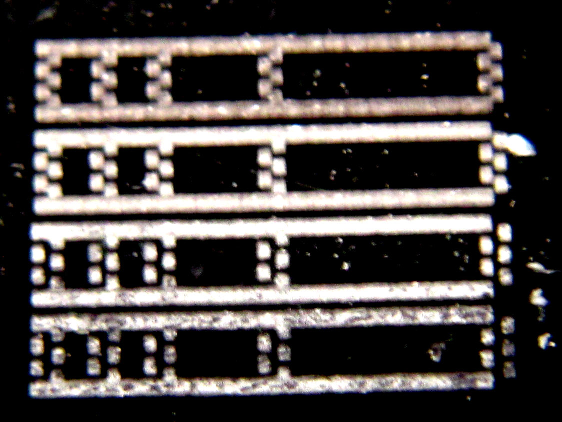
This allows to see how much variation there is between them, explaining what is dependent on time, and what is fixed. After some calculation and tests, it appeared that the pixels when going right to left had to be shifted left by 0.12mm and delayed by 2.6ms. This delay is converted to mm depending on the travel speed so that in the end it gives only a distance.
With the right adjustments it's possible to align left-to-right and right-to-left and almost double the print speed. Here's a capture of the final results. It's still visible on the large rectangle that there can be around 10 µm variations in positioning because the vertical lines are not always perfectly straight, but that's very hard to notice on the microscope, let alone to the naked eye! The one on the right was printed at 0.06mm per pixel, and there the positioning resolution remains imperceptible.

The image of the lunch at the top of the sky scraper at the bottom of this page is 1206x943 pixels, rendered on a visit card of 72x56 mm, and took approximately 25 minutes to engrave. With unidirectional printing previously it would have taken approximately 45 minutes (it's not exactly twice as long because the return can be a bit faster when not engraving).
Beam narrowing
As can be seen on the test image below, the beam can be made narrower when it's a bit taller. This is important because if the beam is as large as a pixel, then when it sweeps an area as large as a pixel, it has effectively engraved two pixels. The image shows a test pattern with one dot every 0.12mm (the ruler is in millimeters). A zoom on the dots shows they're between 25 and 30 µm wide and approx 100 µm tall:

We can then exploit this principle to consider that the beam will imprint larger than desired and consider this for granted as soon as the beam turns on.
Example: let's say we want to print the green dashed line below (each square is one pixel the size of the beam). The laser dot (in blue) by default will scan from the left of the square to the right, and will effectively span twice its size. The part that was constantly under the beam will have received more energy, and the borders which were only a limited time under the beam will have received less. As can be seen as the beam advances from left to right (line after line), the pattern is reproduced but the contrast is limited.

Now if we take that beam width into account, we can make the beam start to light up later and extinguish it earlier, still providing a shadow around the borders but leaving the intervals totally unexposed. This is more efficiently done by having the dots twice as large as the beam and reducing the beam duration in half, as this would then preserve the intervals.


When zooming in macro mode, it's possible to see the dog's hair as 1/16mm dots:

Similarly, a soom at the center/bottom of the lunch photo, zooming on the metallic beam close to a building shows some of the details, then we can zoom further on the beam and it's visible how the gray is obtained by alternating clear and dark lines:


Wrap up
All of this is a question of patience and experimentation. Now I'm able to easily print a photo on metal by using bright black paint and have enough resolution to almost always do it well on the first pass. In the past I had to adjust power, speed, and color conversion to compensate for the risk of too wide pixels ruining everything. That's no longer the case, as can be seen above with direct printing of photos at very high resolution!
No comments:
Post a Comment