
It all started while following some links...
I was having a look at a review for a new single board computer (I don't remember which one) with a link to the Banggood site, and in the suggestions I saw some inexpensive laser modules. Clicking on them by curiosity revealed this appealing laser engraver that made me wonder whether I'd really need it... It turns out that I've been imagining for a very long time that I could possibly make PCBs either by directly printing on presensitized copper boards, or by painting a board in black and then burning the paint. At this price (around 200 EUR then, it went down further since), I didn't risk much so I decided to order it.Receipt and assembly
I received it in a quite small parcel, the kit is made of lots of small pieces and long, thin bars. There's no ground plate in it so you have to plan putting something to protect your table. The assembly instructions are a bit scarce, they're made of series of photographs with almost no text in EleksMaker's wiki. But actually the photos are well detailed and almost everything is pretty straightforward. My friend Benoit's kids were impatient to see it so I thought it could make a good week-end activity to let them assemble it, thus I waited for the next week-end and verified I had everything available. On the next week-end, they came and I opened a browser on the wiki with the instructions and let them do the work. They're 8 and 11, don't read English, and it took them two hours to assemble everything with no help (actually yes, they asked me to tighten the screws of the controller board as they were afraid to risk to damage it). I was impressed by the result, they even managed to properly tighten the wheels on the bars so that the motors could move smoothly without shaking. It's really nice when you see that such a device can be assemble by kids, it means the instructions are pretty clear and universal!
There were some extra parts at the end, that reminded me a re-assembly of something I'd have disassembled... Initially that worried me a bit and I realized that it was on purpose, in case you break or lose one. Such extra screws and nuts are welcome for later improvements. And as a small plastic box is provided to hold them you don't risk losing them.
The part on the cables assembly is not obvious, it never appears on the photos. We tried different approaches. Leaving all the cables floating around is not convenient because they tend to catch anything around. Passing them all in the provided plastic roll makes too rigid an assembly. I finally figured that passing the Y motors' cables inside the lateral frames and attaching the laser and X motor inside the plastic roll was almost the best solution.


Build quality
I was really impressed by the build quality, especially for the price. I had expected something a bit flexible or shaky but no, it's extremely rigid, everything holds well in place and moves smoothly. There are no tension areas and the axis move perfectly parallel to the frame.I don't like the cable passing method at all. The one on the sides is far from being perfect, with the cable falling under its weight and occasionally getting stuck between the plastic block and the frame. It doesn't happen often but when it does it ruins what you were doing. And the plastic spiral to hold the X motor and the laser cable together isn't completely smooth due to being rolled around the cables, and tends to occasionally force either against the plastic part of the controller, or against the X motor's fixation. I found that making it arrive by the right of the motor and using the laser's cable to hold it in place is what gives the best results. But it can happen, I'd say in 2-3% of the operations, that you hear your motors "jump" and miss a step because this spiral got trapped somewhere. This really is not anything to worry about at all, everyone will find their own solution to this.
A support is missing, and you have to put something riskless under the engraver. I initially used a glass plate on top of a thermal protection for ovens. Then I made a support using 2 aluminum corners to serve as a support for the glass, thinking it could also serve as a ruler, but it immediately became much more complicated to align stuff on this because we'd lose some degrees of freedom:

Then I thought that some marble could be nice as it would cast the light once the material is cut without risking heating, but finally went for a thin 40cm*40cm concrete slab apparently made for walk paths in gardens. And it was very cheap (4.5 EUR).
A few security rules
If you consider that you'll be careful and will never damage the table under the machine so you don't need a protection, you're wrong. The laser is turned on during resets or certain operations. It can also hang turned on due to a software bug. You definitely want something which can dissipate 2.5 watts of power in a 50th of square millimeter. That's roughly 125000 times the light density that reaches the ground in summer under the mid-day sun (at 1000W/m²). By the way, protection glasses are MANDATORY.

They are mandatory for two reasons. First because you never know if you'll get a reflection. Second because the light point is so small and concentrated that you don't feel blinded by staring at it, but it destroys your eyes. I found that working on the device one evening despite wearing the glasses was straining for my eyes. So you really want to be careful. And take care to work a very bright room, this will further protect you by having your pupil almost closed, compared to being wide open when working at night. The glasses provided by default do not offer a very good protection to be honest, but you can actually watch a piece being made with them if you don't stare too long. Red ones are easily found on the net and protect much better. However they protect so well that you don't see much around and you develop a higher sensitivity (your pupil extends). So in the end I found a better comfort with the green ones. It's possible to stack them on top of each other for an increased protection but then you won't see anything else.
I found that illuminating the piece being etched with a strong concentrated beam of powerful light helps a lot while observing. You even get a clearer image.
And if you're working on something too bright or with reflective parts inside, don't look at the beam, use a camera instead. You can easily replace a dead camera, you cannot easily replace a dead eye.
Very first tests
The difficulty starts right here. Laser engravers, like 3D printers, use a language known as G-Code to describe the moves. I've never used G-Code before, and have zero experience with the required software. The vendor's site suggests to use their EleksCAM software, but I couldn't find it on their site, it looks like you have to create an account on the forums to find the download link, and I'm definitely not going to create one other account on yet-another-site just to download a piece software, which apparently is only for Windows, which I don't have.Digging on the net quickly drove me to a number of important software parts:
- GRBL G-Code parser and CNC controller, which is the software running inside the controller on the board. It is important to know this because there are some variants betwen language implementations and it's better to make sure other software are compatible. The device is shipped with version 0.9 of the software.
- UGS (Universal G-Code Sender), which is a Java-based application made to send some G-Code to a device over a serial port
- J Tech Photonics' plugin for Inkscape, allowing to convert any vector drawing to G-Code
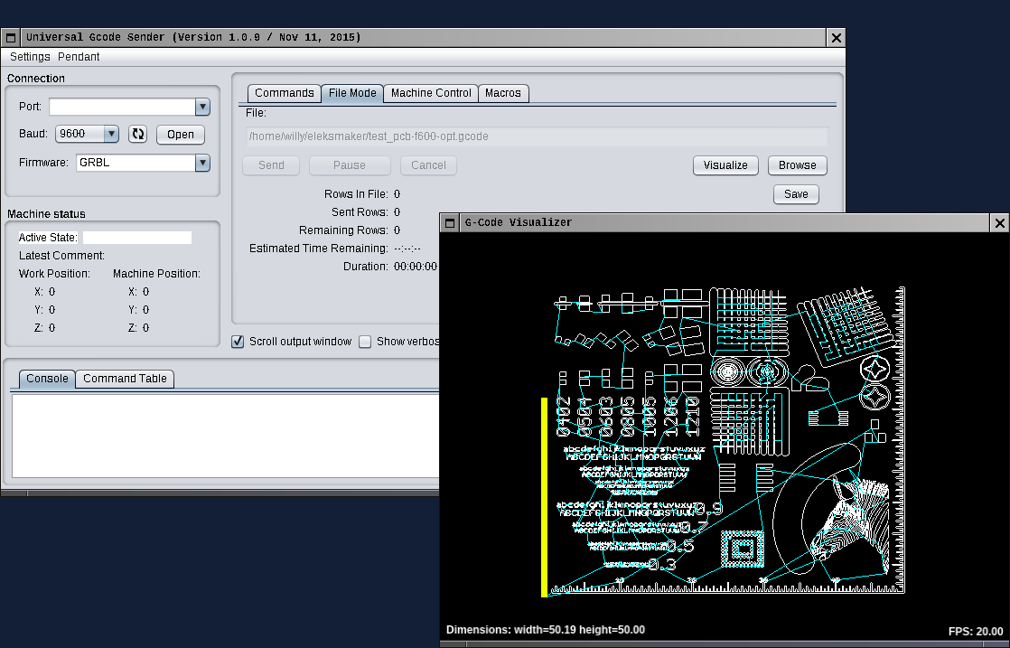
I also found quite a useful test file called "test_pcb" on this page, producing the test pattern appearing below (I hope it's OK to show the image here):

It brings the benefit of allowing me to first test the hardware and low-level stuff before having everything ready.
I found UGS "classic" to work "well enough". It's a bit heavy and you hear your laptop fan spin when it works, and it spews hundreds of Java backtraces into your terminal while it operates, but it has the merit of being cross-platform and apparently not crashing. Also it gives you access to the G-Code console where you can send directly commands to GRBL, so it's convenient to use to report some settings, move the head or turn the laser off/on.
I found that the "reset zero" operation didn't work, but this was a limitation of my old firmware (0.9) which was later addressed. So I just had to first go to zero position, then move the axis by hand where I wanted. I figured moving the axis by hands is not a good idea because the controllers support a mechanism called micro-stepping, and when you move the motors by hand, you simply "reset" all possible micro-step that the motor might have engaged. Also it's possible to get the left and right motors slightly shifted, thus having the X axis not perfectly parallel to the frame. It's better to use the arrows or X/Y buttons to move the head, then power the laser off, click "goto zero", and power it on again.
Then I wanted to give the J Tech Photonics plugin a try. I downloaded some test SVG images from the net. These are not always easy to find, most links are squatted by vendors who want to charge you for a small image, or by links to this crappy Pinterest site which suddenly sends you a modal pop-up forcing you to either create an account or click "Back". Despite this I easily found various ones including an HAProxy logo, an ant, a ruler, an Eiffel tower Kirigami (to make card board unfold in 3D), and a lot of freely downloadable and well categorized images here at onlinelabels.

Selecting everything and clicking "Extensions/Generate Laser Gcode/J Tech" proposed me a number of options to generate some usable G-Code. I experimented with various speeds, numbers of passes etc. The "travel speed" is the maximum speed at which the axis may move when the laser is off, and "laser speed" is the maximum speed at which the axis may move when the laser is on.
The travel speed depends on the hardware build quality and motors power and precision. Traveling too fast results in imprecise movements. I found that I shouldn't go over 2400mm/min to keep accurate moves. That's 40cm/s so it means one second to go from full left to full right. That's fast enough for almost anything.
I observed that the laser speed heavily depends on the material used : moving too fast doesn't even mark because the material doesn't have the time to heat enough to vaporize or melt. Moving too slow can easily make the material catch fire. In this case it's better to pass faster with a lower power and run multiple passes. I found that speeds around 400mm/min were perfect to cut paper and thin cardboard in a single pass without ever catching fire. Cork and light woods tend to catch fire almost instantly.
The plugin is a bit confusing to use at first because it draws the paths onto your artwork and displays some coordinates on top, that you have to manually select and delete afterwards:

A few times I managed to render the G-Code not for my object but for the previously produced path, so that can be a bit awkward when you don't know but is not a problem once you got used to deleting these.
Sometimes the path doesn't appear just because it's at a totally different location. In this case just press Ctrl-A to select everything an you'll generally see it caught by the selection. Apparently it's how most Inkscape plugins work. It's not necessarily bad but you need to get prepared to this and think about saving first. Another hint is that the plugin will not produce any valid content if you open a file that is not part of a layer, so you need to see a later in the layers dialog. In this case, just select everything (Ctrl-A), copy (Ctrl-C), create a new document (Ctrl-N) and paste at the same position (Ctrl-Alt-V). Also don't use the plugin with multiple Inkscape documents open, or you never know which one will be rendered (it's not necessarily the one you're seeing and I still have to figure how it choses which one it renders). It's particularly troubling when working with multiple versions of the same artwork and you can't seem to observe the effect of your changes. And since testing G-Code tends to be destructive in that you have to burn some material to compare the results, you generally prefer to stay on the safe side and limit uncertainty.
It's also important to note that Inkscape is still in very active development. My version was 0.92.1, I had too many issues, upgraded it to 0.92.4 and while it's better, it still rarely works more than 5-10 minutes without crashing if I'm not careful. I found so many situations causing it to crash that if I wanted to start to file bug reports I wouldn't even know where to start nor how to describe what I was doing :-( At least it's kind enough to save your work when it crashes. What I figured is that you must never ever undo an operation, you have 50% chances that it crashes (that was my first attempt to get rid of the extra paths lefts by the plugin), and each time you open an bitmap image (png, pdf, ...) you're taking risks as well (I suspect I'll end up being able to describe a reproducer for this one which is extremely frequent, I don't remember having successfully opened more than 2 images in the same session):

There are issues when importing PDFs, where units displayed on the ruler do not match the ones displayed or that use use, and even if you change them, each time you save, they're switched back to "px". I found that selecting and copying the artwork into a new document and saving it as SVG would often fix these issues. The interface is not intuitive at all for a beginner since many disallowed operations simply do not give you any feedback nor hint, so when you fear you did something wrong you press Ctrl-Z and either lose some work, or see it crash. Once you get more used to it you tend to be extremely careful to avoid such operations, you save more often and it crashes less often.
Despite being extremely annoying for these issues, it's still worth making the effort of trying to use it without getting discouraged, because even if it does have a long learning curve, it's powerful and heavily documented on the net (even though most tutorials are painfully long videos instead of just saying "press Ctrl+Shift while doing this or that").
And for PCB ?
[Update: full article covering PCBs from A to Z now posted here]Then I tried to play with a PCB I made under Eagle. That's where I understood I was going too far. One first needs to understand that Inkscape works with "paths". Objects, pixels or anything are totally irrelevant, what matters is the vectors you're making with your pen on the paper in some sort. When you import an image, you can't do anything useful with it by default. And importing a PDF only makes an object from which you cannot derive a path (other than the rectangle surrounding the image). There are examples on the net explaining how to detect edges on such an image to make a path but these required a menu entry that I didn't have under "Path", which is "Trace Bitmap" (not to be confused with "Trace Pixel Art" which is something different).
I later figured that Inkscape had to be built with "libpotrace" installed to have this, so I ultimately rebuilt it from latest sources after installing this library (both of which went amazingly well by the way). Anyway there's quite some value in rebuilding Inkscape, as bugs are reported and fixed almost every day so by staying up to date you avoid a lot of them).
Thus I attempted to export the bottom layer of my PCB in Eagle as a PDF, then to convert this PDF to SVG using "pdf2svg", then import it into Inkscape, to realize that it had lost all the tracks' width and they were replaced by thin lines! It was not Inkscape's fault as ImageMagick would display the same lines. Then I tried again by exporting the layer as a PNG, using "potrace" to convert it to SVG, open it in Inkscape and convert it to a path. This actually worked pretty well, but I had to figure the scale myself and resize the shape appropriately. I later figured that superposing the unusable PDF version and the SVG that I was resizing would significantly help to provide the scale.
I could produce the G-Code needed to draw the tracks' contours, send it using UGS to the engraver over a mate black-painted PCB, cleaned it under water and watch the result:


There were two defects where some tracks ought to have been straight but one side followed an arc. I suspect it's a combination of the path detection and the plugin because on the screen this issue doesn't exist. At first glance this wouldn't prevent the circuit from working.
One very cool aspect of working with paint is that if you don't like the result, you can clean it and try again. I was fine with this one so I sent it to the ferrochloric acid bath to etch it and test the result.


Now looking back to this I'd say it wasn't terrible, because I did so much better since. But actually I was impressed. At first glance, the cut around the tracks was 0.12-0.13 mm wide. Some copper tracks less than 0.1 mm wide were left intact. I didn't select a specific speed and roughly tried to properly focus the laser. The rounds in the holes were a pain to drill, I had to use a cutter to remove the copper first. And the circuit actually worked! I never had this level of precision before. Just to provide a scale, the 8 rectangular pads in the center are an SOIC8 microcontroller, the pitch is 1.27 mm. And on the left there's a mini-USB connector which is half that, it's 0.635 mm, with around 0.315 mm between two pads. The copper left in the middle between two USB pads is around 0.08 mm and the space is around 0.12 mm. Some issues definitely need to be addressed but the initial goal was already met!
Going further
I tried other G-Code senders, such as bCNC which is very complete and even allows you to edit and fix the G-Code, but relies on multiple views from which you have to navigate a lot. There's also "UGS Platform" which is the next version of UGS. It's supposed to support a feature called "jogging", consisting in pointing to a location on the artwork and move the head there, which is important for centering, for example when making double-side PCBs. But for me the menu entry is always gray and I cannot click it.I found that all of them (UGS classic, UGS platform and bCNC) would occasionally hang during a complex drawing, leaving the laser on. I think I figured what happens in this case. The software are actually not frozen, I can send a reset to the controller. It is that the byte stream is too fast and they likely fills GRBL's buffer, causing some characters to be lost, and the firmware is then waiting for the end of a command (likely an LF) that never comes. Maybe their flow control is not perfect, or they don't well respect the output status from GRBL. I later found SourceRabbit G-Code Sender which does not suffer from this issue at all. But its visualization window actually never displays anything so you cannot easily control what's being done. Its progress bar is more accurate though.
While trying to work around transfer issues between Eagle and Inkscape to maintain scaling and avoid issues with improperly converted tracks, I finally found an excellent plugin for Eagle, which is called "pcb-gcode". It's seems to be maintained by a small community though it's difficult to find it for downloads, resulting in many copies floating around. I'm using version 3.6.2.4 from here, and a copy of it was moved to github here, sadly as a single import, thus losing all of its history (no updates since then).
This plugin does something I really wanted, which is to make multiple passes with a growing clearance around the tracks. It produces the G-Code output by itself, for each side, and can even make the stencils needed for the solder cream! Now to be clear, this is the proper way to go to make PCBs using Eagle and the EleksMaker laser machine. The results are purely astonishing and there is no need anymore to switch between multiple formats nor fight with conversion issues under Inkscape. Here's just an idea of what can be achieved with this awesome plugin:

To give an idea of scale, the small horizontal lines in the middle go to a small chip using 0.65 mm pitch, and are spaced by 0.3 mm. Since I didn't use much clearance, it managed to leave some unused copper of around 0.05mm between certain tracks! With proper tuning it must be possible to etch tracks as thin as 0.1mm. I didn't know that it was possible at all with this chemical process.
I also discovered by accident that the device by default uses power level values between 0 an 1000, but the plugins were emitting values between 0 and 255 by default. Thus the machine was operating at only 25% of its power, explaining the hissing sound of the PWM output I was hearing during operation. When pushed at full throttle, the beam is even scarier:

I first made a script to convert the values (G-Code is easily editable), but that's not terribly convenient. After upgrading it to a new firmware version I figured it was possible to change the high and low values in the firmware so I changed them to use the 0-255 range and always use it at full scale. I'm not certain it was possible in 0.9 however. Changing the laser power in the various tools to write 1000 instead of 255 was often enough. I haven't made a PCB at full power yet, so I don't know if it's better for the paint or not. Given that some PCBs can take ages due to the multiple clearance passes, it could make sense to etch them faster at higher power. More experiments and reports on this in another article.
Filling areas and writing text
Writing text is also one fun thing to do with a laser engraver. You can write your name on your mailbox using materials that don't fade away under the sun for example. My first attempt was made by cutting letters in duct tape and sticking them onto a plastic plate. This looked great and is still on my mailbox. But I wondered if it was possible to make plain areas instead using patterns fills.Making a filled shape in Inkscape is not easy. You need to create a pattern made of many lines, extend/replicate it to the size you need, then superpose it with the shape you want to have and play with intersection/difference between the paths to only keep your stock of lines limited to the path of the original object. But this is actually possible. This is what I've used for the tests below (paint on aluminum, then etched using ferrochloric acid):


It's difficult and not very precise, as it's very easy to end up with irregular lines or lines that are not spaced using an integral multiple of the motors' resolution possibly leading to Moiré effect. I started to think that it might be possible to draw following horizontal only lines in "pixel mode", by just modulating the laser while moving. This is actually what 305engineering's Raster 2 Laser plugin does. And it's pretty straightforward to use. It can even adjust the laser's power depending on the luminosity of the pixels to print grayscales. With GRBL firmware in version 0.9, each change of laser power results in a short stop-start sequence causing a small burn. With version 1.1 there is a new "laser mode" which allows the motors not to stop between laser power changes, resulting in a fast and very clean result. This is actually very convenient to print photos, but more or that in another article. Here are a few examples achieved using this plugin:
Funny faces, gradients, Escher drawing, and backs on cardboard or even a toilet paper roll (those having known the Internet in the 90s will surely recognize something which was famous by then). Dense cardboard like is used for food packing is very good at rendering gradients. The lightest ones like toilet paper roll burn on the surface and do not render gradients:


Cat and dog on wood, village on cork, all of them ignite very quickly and are very hard to get gradients :


Symbols on plastic (more on plastic in another article):


Even on crude steak (a proof that you definitely must not put your hand under the beam):

Making wood and acrylic enclosures
One nice purpose I didn't think about and which I've already abused is to make plastic enclosures for various devices. There is an Inkscape extension called "Lasercut Box" which prompts you for a few parameters (dimensions, how much does the laser beam eat, speed and strength) and which produces G-Code that you just have to send to cut acrylic or wood. I initially tried with wood and didn't get good results due to the limited power, even after 12 passes it didn't go through 3 mm plywood. But a new attempt at full power proved it was possible in 6 or so passes (even if the result is not clean). The wood tends to burn under the laser so it's a bit tricky to figure the good speed and power, some experimentation is needed, but it definitely is possible at least:
For plastic, I bought an acrylic transparent red sheet and tried it. The result is marvelous. I can cut 3 mm in one single pass at a very low speed (20mm/min). It's important to perform some tests, like the pattern below I made at various speeds for different squares. I could finally make an enclosure for my NanoPi-Fire3 board!


Conclusion
This machine is really amazing and opens new perspective for working on hard materials, especially for someone not very manual like me. I think I found the tools I needed to exploit it fully (please check the download links in the text above):- G-Code senders: SourceRabbit for raster (very likely to hang with others), UniversalGcodeSender (UGS) for PCBs and regular use, bCNC for stuff that requires manual adjustments.
- for PCBs, I design them in Eagle 7.7 (the last version supporting to work offline), convert them to G-Code using pcb-gcode from within eagle. Since the plugin gives a preview, it's never needed to switch to another application to control the result.
- for drawing and cutting, I'm using Inkscape using J Tech Photonics' extension which is quite simple to use, supports multiple passes and is really stable.
- for images and text requiring filled areas, I'm using 305engineering's raster2gcode plugin and I'm using my device in laser mode with firmware version 1.1 (more on that later).
- for laser cut tabbed boxes, I'm using the Lasercut Box Inkscape extension and found that it was best to configure the Kerf parameter to 0.15mm when cutting acrylic.
Well done Willy !
ReplyDeleteamazing creativity brought to an operational level : it works !
congratulations
keep going, keep searching, keep finding... (less and less) young man !
and top of all : continue to keep yours eyes wide open (sorry Stanley)
Guillaume A
You're so amazing! The resust is wonderful. This is magnificent. Just tremendous!
ReplyDeleteMe too, one day, i'll have an idea!
GREAT information!
ReplyDeleteBuilding mine as I type!
thanks