Background
The MiQi-based build farms had been running very well both at home and at work over the last 2 years. I noticed that some very large files in haproxy totally dominate the build time (notably cfgparse.c), and can keep a core busy from the beginning to the end of the build. It was a signal that this file needed to be split into pieces, but it also made me start to study possibly faster CPUs, including some big.LITTLE combinations.New CPUs
I had been lurking for some time on the fresh new Rockchip RK3399 SoC, featuring 2 Cortex A72 and 4 Cortex A53. These devices were presented either under the form of a quite expensive T-Firefly development board or as various types of TV set-top-boxes. I found a moderately affordable one, the H96 Max. It's easy to get confused since all their devices are called "H96 something" or "H96 max something". Here it's purely "H96 Max", no "pro" nor "x2" nor "h2", like this one. Getting Linux to work on this one proved to be quite a bit of a pain at first. I had to make my own USB A-A cables to access the flash, and solder wires inside to access the console port, then try many different images to find a bootable one (I don't even remember which one worked in the end).

The RK3399 inside us supposed to run at 2.0 GHz for the big cores and 1.5 GHz for the little ones. As usual with this type of devices this is a lie, it's only 1.8 GHz for the big ones and 1.4 for the little ones.
Despite this, the performance was attractive as it reaches the same performance level as the overclocked MiQi. It's also visible in this performance report that the 4 little cores deliver together the same performance as the 2 big ones, meaning that the 2 large cores at 1.8 GHz have roughly the same performance as 2 overclocked cores on the MiQi.
But if the larger files landed on the A53 cores, then it was a disaster, with the build taking too much time. At 1.4 GHz, an A53 takes roughly twice the time to build a file than an A17 at 2.0 GHz. So this device was overall faster but could be up to twice as slow depending on the scheduling. I continued to explore it a little bit.
I later figured that there was a memory controller tuning issue with this board. It runs on LPDDR4 but is configured by default with low performance settings like 200 MHz or so! Also there is some arbitration to access the L3 cache between the little and big cores, and the little cores get a very low bandwidth, which explains a number of things. By then I didn't figure how to work around all these limitations.
Then came the NanoPi Fire-3. It's exactly the board I had been waiting for for 2 years. It features 8 A53 cores on a very small size, and there is no wasted component on it. I bought one, found the CPU was designed to be 1.6 GHz, thus I set it to 1.6 after adjusting the thermal throttling levels, and found this board to be a much better performer than the A53s in the RK3399. However, while this board probably holds the performance-to-price award, it's not faster than the MiQi so I didn't want to "upgrade" the build farm with it, it wouldn't make sense.
After HardKernel released a new version of their Odroid boards called the MC1, specifically designed for clusters, I decided to give it a try as it was perfectly matching my needs. And the Cortex A15 was supposedly fast, and running at 2 GHz there. I found that while the CPU is indeed pretty fast, its memory performance was one third of the MiQi's, which is not surprising given that tha Cortex A17's main improvement over the A15 was supposed to be a completely revamped memory controller. The build time heavily depends on memory performance, so the board was only as fast as the MiQi with stock settings. I would have built the farm out of it if I hadn't had the MiQis though, as it's much less hassle to cool it down.
The NanoPi Fire-3 experience made me realize that the Cortex A53 wasn't that bad if it could be driven at a higher frequency and with a correct memory controller. The main problem is that it's often used in low-grade chips for which vendors are lying a lot regarding frequencies. I noticed the new Allwinner H6 supposedly running at 1.8 GHz, so I decided to order an Orange Pi One Plus featuring it. It indeed ran at this frequency, but the performance was a disaster, due to very poor memory performance.
A few days later, once at Haproxy Technologies we had assembled our new network benchmarking featuring many SolidRun MACCHIATObin boards, I couldn't resist the temptation to install my build tools on them for a test. And this board featuring four 2.0 GHz Cortex A72 cores was the first one to be faster than the MiQi at the same frequency. 20% faster to be precise. It's easier to cool and has the same number of cores. The board is much more expensive than the MiQi but this convinced me that the A72 could do the job.
Past the holidays period, FriendlyELEC issued their long awaited NanoPi-M4 board, which by then was the smallest and cheapest RK3399 based board. And it was perfectly designed, like many of their boards, with the CPU on the right side (the bottom) to ease cooling. It was the same price as a MiQi, but included the huge heat sink. Knowing that I would have everything I needed (docs, schematics, source code), I immediately ordered one. The result was quite good out of the box, the same as the stock MiQi. With proper tuning I found that the big cores would accept 2.2 GHz and the little ones 1.8 GHz, but not with the big at 2.2 at the same time. It was OK with the little at 1.8 and the big at 2.0 though. These little cores are the most important ones for the build time in fact. And the new record of all times was easily broken here with 14.5s vs 17.6. It was even slightly faster than the MCbin. So now I knew what board I was going to order :-)
The new board
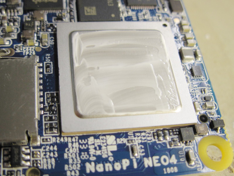
Slightly later than the NanoPi-M4 FriendlyELEC issued an even smaller and cheaper model, called NanoPi-Neo4. For only $45 you get this tiny board with these 6 powerful cores. I noticed that the board's layout easily allows to mount them vertically with all connectors on one side and the heat sink behind :
I soon saw they had a discount for the Black Friday period and after thinking a bit how to arrange them into a farm, I decided to order a bunch of them, 5 to be precise. But I was limited to two on the site! I asked them about this limitation and they very kindly offered me to participate to my build farm setup by offering me the 3 extra boards I needed. This was awesome! I remained very reasonable, with only the boards, an eMMC module to host the operating system, and the USB power cables because I know that just like with MiQi, their cables are of excellent quality. I didn't even take the heat sink because I had other plans ;-)
New build farm layout
The ability to stack multiple boards vertically as close as possible from each other was extremely appealing. I realized I would only need an L-shaped aluminum block to connect each board to a larger common heat sink. I spent some time looking at DIY stores and finally found what I was looking for : 5.2cm wide and 2mm thick aluminum corner :

Once sawed it perfectly fits :


Then I drilled the holes for the screws :


One issue remained : the SoC is thinner than the micro-SD card reader. I expected to directly put thermal paste on it but it will not touch the aluminum plate so I need a thermal pad :

I didn't want to use soft thermal pads since I know they are not very efficient. For a test, I started with some ceramic pads that I had :


The result was OK, the CPU was touching fine :

I assembled everything and I ran some tests with cpuburn to verify that it was OK (and it was) :

But my thermal pads were not all the same and I preferred to switch to copper pads later to better conduct the heat through the aluminum with less losses (copper having a lower thermal resistance than aluminum). For this I wanted the pads to be as large as possible. I sawed a 10cm wide 2mm thick copper plaque I had, into almost identical 3.2cm wide pieces, and polished them. Also, since the CPU is close to the edge of the board, the thermal pads need to have a notch on one corner so that the screw can pass.
It's a real pain to saw thick copper by the way, because it is ductile and doesn't stay perfectly flat when attacked with a saw. Next time I'll try with a thinner plate. From my measurements, 1mm should be way enough. But eventually I had my 5 copper thermal plates in place:


Finally it's starting to look like a build farm:

I found that the thickness of my thermal pads could be an issue for the board, because I didn't want to force too much on the screws but still I wanted the board to firmly press the CPU onto the pads. I opted for some form of soft fixation. For this I've cut some springs, placed them between two washers on a screw. This allows me to adjust each screw individually without risking to bend the board too much. This is important because you definitely want to use as little thermal paste as possible to make the best quality contact, and for this to be possible you need the CPU to firmly press on the pad :


Now all boards could finally be prepared, and the final shape starts to become visible :

I needed to find a large enough heat sink to place behind without disassembling the previous farm which still works fine. I opted for and old Pentium2 heat sink which happens to be of the exact same width as the set of boards:


I figured that it would be pretty difficult to fix the boards using screws to this device. So instead I've used a large band of thermal tape, the same that I used with the MiQis. It's not perfect but it's good enough if you press firmly to attach the boards and cover all the surface with it:


The resulting assembly makes a nice compact block:

This new cluster is finally ready to replace the previous one in the home cluster:


Installation
I simply installed the default image from the FriendlyELEC wiki dedicated to this board. Since I already had the micro-SD to eMMC adapter, it was fairly straightforward to download the images and copy them there :
I had to disable a lot of the systemd related crap that eats CPU for nothing or wants to have fun with your nerves by being creative with your network setup, as well as disable graphics mode which eats memory for no reason in this specific use case :
# for i in gpsd ModemManager bluetooth dnsmasq systemd-resolved.service networkd-dispatcher.service; do
> systemctl disable $i; systemctl  stop $i
> done
# apt-get remove wpasupplicant
# apt-get remove lightdm
This way I could have my own network setup with static IP addresses, my own resolv.conf, and have better control over what is being done, without the fear that WiFi would suddenly turn on and expose the boards to the net for example...
I did a mistake you must not reproduce : I first installed one board and duplicated its flash to make the other ones. This resulted in all boards to have the same MAC address because it's U-Boot which randomizes the MAC address in its config upon first boot (which is quite convenient by the way).
I found where U-Boot's environment is stored and was able to destroy its checksum from the command line, getting a new random MAC address on next boot :
# dd bs=1 count=4 seek=$((0x3f8000)) of=/dev/mmcblk1 if=/dev/zero
My boards are named "neo4a" to "neo4e". Given that there's plenty of room on them (8 GB), I've installed several compilers for various target architectures and in different versions. The ones provided on kernel.org work almost out of the box there, there's only a symlink to add from libmpfr.so.4 to libmpfr.so.6. I've installed versions 6.4 and 7.3 for i386, x86_64, arm, aarch64. And I've standardized the names like this : <target>-<gccversion>-linux-gcc for ease of use and so that they could match similar names I use on my build machine while masquerading by distcc :
$ ls arm*
arm64-gcc-7.3.0-nolibc-aarch64-linux-gnu.tar.xz
arm64-gcc-7.3.0-nolibc-arm-linux-gnueabi.tar.xz
arm64-gcc-7.3.0-nolibc-i386-linux.tar.xz
arm64-gcc-7.3.0-nolibc-x86_64-linux.tar.xz
arm64-gcc-6.4.0-nolibc-aarch64-linux-gnu.tar.xz
arm64-gcc-6.4.0-nolibc-arm-linux-gnueabi.tar.xz
arm64-gcc-6.4.0-nolibc-i386-linux.tar.xz
arm64-gcc-6.4.0-nolibc-x86_64-linux.tar.xz

$ HOSTS=neo4{a..e}

$ for c in arm64-gcc-6.4.0-nolibc-*xz arm64-gcc-7.3.0-nolibc-*xz; do
> echo $c
> for h in $HOSTS; do
>   ssh $h "sudo tar -C /opt -Jxf -" < $c
> done
> done

$ for h in $HOSTS; do
>   ssh $h 'sudo ln -s libmpfr.so.6 /usr/lib/aarch64-linux-gnu/libmpfr.so.4'
> done

$ for h in $HOSTS; do
>   ssh $h 'for f in /opt/gcc-*-nolibc/*/bin/*-gcc; do v=${f#*gcc-};v=${v%%-*};v=${v//.}; n=${f##*/};sudo ln -sv $f /usr/local/bin/${n/-linux/-gcc$v-linux};done'
> done

$ sudo ln -s /usr/bin/gcc-7.3.0 /usr/local/bin/x86_64-gcc730-linux-gcc
$ ln -s /usr/local/bin/distcc /home/toolchains/x86_64-gcc730-linux-gcc
$ cd linux
$ make -j 60 CC=/home/toolchains/x86_64-gcc730-linux-gcc bzImage modules
Optimizations
I tried to push the CPUs to their limits and found that one of the boards didn't like to have its little cores run at 1.8 GHz, but was perfectly OK with 1.7. However it's OK with the big CPUs at 2.2. In the end, in order to ease maintenance, all boards have been configured to run at the same speed, 2.2 + 1.7, which I'm setting using this script (some kernel patches are required to get the extra frequencies, see below) :# cat set-speed-neo4-1.sh
echo 2 > /sys/kernel/debug/clk/sclk_ddrc/clk_enable_count
echo 928000000 > /sys/kernel/debug/clk/sclk_ddrc/clk_rate
echo 1 > /sys/devices/system/cpu/cpufreq/boost
echo 1704000 > /sys/devices/system/cpu/cpufreq/policy0/scaling_max_freq
echo 2208000 > /sys/devices/system/cpu/cpufreq/policy4/scaling_max_freq
echo performance > /sys/devices/system/cpu/cpufreq/policy0/scaling_governor
echo performance > /sys/devices/system/cpu/cpufreq/policy4/scaling_governor
echo performance > /sys/devices/platform/dmc/devfreq/dmc/governor
I tried manually to increase the thermal thresholds to limit throttling with good success until I moved them into the DTS :
# cat set-temp.sh
echo  85000 > /sys/class/thermal/thermal_zone0/trip_point_0_temp
echo 100000 > /sys/class/thermal/thermal_zone0/trip_point_1_temp
echo 115000 > /sys/class/thermal/thermal_zone0/trip_point_2_temp
Pushing the limits
In order to play with the board, you need to clone the board's kernel from FriendlyELEC's GitHub repository here. The branch to use is "nanopi4-linux". The procedure is described in the wiki here.When you build the kernel using "make nanopi4-images", you'll get three device tree images in one single "resource.img" file. It is important not to try to build your images by hand and to use the appropriate make targets, as you absolutely want the device trees blobs to be appropriately named. Indeed, the boot loader looks for their respective names in the resource partition. Their names are as follows :
- rk3399-nanopi4-rev00.dtb for the NanoPC-T4
- rk3399-nanopi4-rev01.dtb for the NanoPi-M4
- rk3399-nanopi4-rev04.dtb for the NanoPi-NEO4
If you want to add new frequencies for your board, you have to modify the respective DTS. It is strongly recommended to only add them as "turbo-mode" entries, so that they are not picked by default unless the "boost" variable is set. This way the board can boot safe and only hang once you enable the new frequency. Example with this patch adding 1.6, 1.7 and 1.8 GHz operating points to the little cores :
diff --git a/arch/arm64/boot/dts/rockchip/rk3399-opp.dtsi b/arch/arm64/boot/dts/rockchip/rk3399-opp.dtsi
index 12c95c7..483ec24 100644
--- a/arch/arm64/boot/dts/rockchip/rk3399-opp.dtsi
+++ b/arch/arm64/boot/dts/rockchip/rk3399-opp.dtsi
@@ -130,6 +130,36 @@
                        opp-microvolt-L3 = <1100000 1100000 1200000>;
                        clock-latency-ns = <40000>;
                };
+               opp-1608000000 {
+                       opp-hz = /bits/ 64 <1608000000>;
+                       opp-microvolt    = <1225000 1225000 1225000>;
+                       opp-microvolt-L0 = <1225000 1225000 1225000>;
+                       opp-microvolt-L1 = <1200000 1200000 1200000>;
+                       opp-microvolt-L2 = <1175000 1175000 1200000>;
+                       opp-microvolt-L3 = <1150000 1150000 1200000>;
+                       clock-latency-ns = <40000>;
+                       turbo-mode;
+               };
+               opp-1704000000 {
+                       opp-hz = /bits/ 64 <1704000000>;
+                       opp-microvolt    = <1250000 1250000 1250000>;
+                       opp-microvolt-L0 = <1250000 1250000 1250000>;
+                       opp-microvolt-L1 = <1250000 1250000 1250000>;
+                       opp-microvolt-L2 = <1225000 1225000 1250000>;
+                       opp-microvolt-L3 = <1200000 1200000 1200000>;
+                       clock-latency-ns = <40000>;
+                       turbo-mode;
+               };
+               opp-1800000000 {
+                       opp-hz = /bits/ 64 <1800000000>;
+                       opp-microvolt    = <1275000 1275000 1275000>;
+                       opp-microvolt-L0 = <1275000 1275000 1275000>;
+                       opp-microvolt-L1 = <1275000 1275000 1275000>;
+                       opp-microvolt-L2 = <1250000 1250000 1250000>;
+                       opp-microvolt-L3 = <1225000 1225000 1225000>;
+                       clock-latency-ns = <40000>;
+                       turbo-mode;
+               };
        };

        cluster1_opp: opp-table1 {
Please be very careful regarding the voltages. The CPU's spec v1.6 indicates that the recommended operating voltages is 1.25V for the big cores and 1.20V for the little cores, with an absolute limit of 1.30V for any internal voltage. I found that using the same voltage for the core and L0 cache worked fine, and that having a decrease of 25mV per cache layer was fine as well. The lower the voltages, the lower the heat.
If you want to add extra frequencies, you have to modify the clock driver.
In my tests, in order to keep the high frequencies stable even at high temperature, I had to further increase the voltage. The little cores run at 1.30V at 1.7 GHz. Upper frequencies do not work reliably, even at a higher voltage, and I don't want to go beyond 1.35V. The large cores run reliably at 2.2 GHz under 1.35V however.
EDIT:
After this article was caught here suggesting the hardware being used to mine crypto-currencies, I tried to run the cpuminer utility on the boards and found it quite interesting to validate overclocking : it stresses the hardware and can easily crash the boards under excessive overclocking. I found that two boards were not reliable above 1512+2016 MHz and that the 3 others were not above 1704+2112. They have now been re-adjusted and the utility was run for a whole night without a single crash. Those willing to reproduce such a setup are encouraged to do the same. The command used was "cpuminer -a rainforest --bench" (apparently the algorithm is optimized to fill the ARM's pipeline). Probably that openssl speed -multi would work as well, but it cannot run forever.
My patch was based on kernel version 4.4.138 from August 2018. The newer version is based on 4.4.143, but I met a boot issue after I changed the kernel and my config (I haven't checked the cause yet). My patches are available here and still apply and work well with the latest kernel though.
Possible improvements
There's always room for improvement. The first one is that I have to rebuild the toolchains to run in ARMv7 mode. In the past I noticed that they can be up to 15-20% faster in this mode.The Clearfog board is really nice, but it's overkill for this job. Given that all files are compressed using LZO, the bandwidth is now much lower than what it used to be 2 years ago, and peaks at around 170-250 Mbps only. I'm pretty sure that a NanoPi-NEO2 with its enclosure and OLED would make a perfect fit for the build controller in this case : a farm could then be made of 5 NEO4 boards and a NEO2 connected to a 8-port gigabit switch like this one I ordered for less than $20, having one port left to connect to the network, and another port left to daisy chain to anything else. It could be installed on any desk or allow to chain multiple build farms and increase the capacity. The power supply would still remain an issue though.
Another thing I missed was a reset button on the boards. During the first overclocking attempts, it was annoying to have to pull the USB connector. I think a small reset button even if not very accessible would significantly help.
The cooling could be performed differently : the L-shaped aluminum plates could drive the heat to the bottom, where they would screwed to a thick aluminum plate serving as a stand and collecting heat for a large rear heat sink. This would remove all the thermal tape and allow all parts to be tightly screwed and much better conduct heat. It would not be difficult to experiment with using the current hardware since the board's fixing holes represent a square thus can easily be rotated 90 degrees :

Update (2019-04-07): I've finally done exactly this, result is here.
Conclusion
This constitutes a nice upgrade to the previous farm and I feel more confident hacking a bit with it thanks to the removable eMMC that I can easily re-flash from my PC. The boards are easy to hack on since all sources and docs are available, which is a real joy. I'll upgrade my NanoPi-M4 to try to support 1.7+2.2 GHz stable and bring it into the farm. The previous MiQi boards have now completed my office build farm, which is great as well.The USB-C power cables are much more reliable than micro-USB based cables. I thought that the amperage would be limited since the board runs exclusively on 5V but no, it's very reliable.
I'd really like to thank FriendlyELEC for their participation to this project. It's fun but it's also pleasant when you know that it's being watched because it drains interest including from the vendors!
I got an arduino with ethernet port controlling a 8-channel relay on my raspi cluster. all raspi's usb power wire is lead through that relay, so i can turn them on and off easily. serial consoles are all connected to the first raspi via a hub.
ReplyDeletemy tests are a bit more destructive, and then the serial console really helps.
Oh I agree. If I were using this farm for boot testing for example, that's definitely one of the options I'd consider. I'd add that nowadays you can even replace the relays with a power MOSFET. I also developed a USB-based watchdog (published somewhere in one of the 2018 articles), that could easily be adapted for this.
ReplyDeleteThis comment has been removed by the author.
ReplyDeleteI use 20 tv boxes with amlogic S905X3 cpus (1,8Ghz quadcores) in one of my towers. Got them for $30 each, 25 units.
ReplyDeleteReplaced the cooling solution with a decent heat sink and each 80mm case fan cooling 4 units.
Powered via a 200W usb hub (30 port). Each unit uses between 1W idle, to 2.5-3W under full load. Add 0.5W for the fan (per 4 units), and 0.5W on losses, and theyre sub 4 Watt per unit, doing compite tasks.
The S905X3 is an excellent SoC in terms of efficiency. You can get reasonably decent build performance on a few watts with it. However, like with all low-power chips, you need to have a large project with many small files in order to benefit from such a design. You're getting 72 GHz of A55 cores, that's already quite good. Very often however the DRAM bandwidth in such boxes could be a limiting factor, but with 4 cores that's probably not that much an issue.
ReplyDelete