After starting to use my
laser engraver, I found a few points that really needed to be improved.
[
Update-2024-07-30: new resolution and accuracy improvements described here: https://wtarreau.blogspot.com/2024/07/improving-laser-engravers-resolution.html ]
Seeing under the piece
First, when cutting thick material like wood or acrylic, you never know if the cut is finished or if another pass is needed. This is the reason why I installed a 39x30cm glass on 47cm long aluminum corner frames, that I fixed using the extra screws and bolts that were provided with the A3 Pro kit. I had to drill a few corners from aluminum blocks to hold everything in place but aside taking measures and drilling at the appropriate dimensions, there was nothing really difficult:
The first frame I used was quite large (5cm), hoping that it could be used as a ruler, but that was a bad idea since it prevents the beam from reaching the medium beneath, so it is not possible to see if the material is entirely cut or not:
So I finally replaced the large frame and opted for a very narrow one (7mm), which has the additional benefit of having a thin line roughly 4mm from the edge. This further helps aligning the beam with a reference position anywhere on the X axis:
This one is still slightly thicker than the glass so that it can be used as an alignment ruler. However its metal is also thinner thus the frame is quite soft, and adding some weight on the glass can slightly bend it and slightly degrade the focus. Maybe I should have stacked two of them to improve the rigidity.
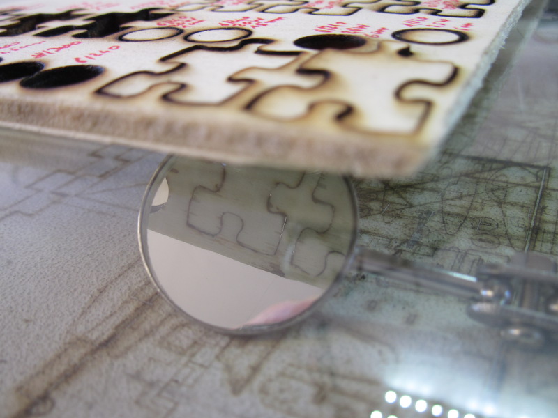
I bought a cheap mirror mounted on a telescopic stick that's made to look for objects fallen behind furniture, it's perfectly suited to looking under the piece being cut (typically with wood you never know when it's finished because even if the beam passes through it's not necessarily sufficient):
Keeping objects in place
As mentioned above, it is preferable to use paper tape rather than weights to keep objects in place. The tape I'm using is sold in any DIY shop to protect walls and windows when painting, it doesn't stick too much and doesn't leave an trace when removed:
It is very convenient to keep objects in place. But when you discover that the cutting didn't completely go through, it's hard to place the object again at the exact same place and angle. At least having one side of the material wedged along the edge frame forces the angle so that by running the engraving process again at low speed and low power, it is possible to progressively slide the object until the beam perfectly enters the existing trench. For other situations like PCBs where it can be required to flip them over when engraving both sides, I found that attaching another small part of aluminum frame along the right Y axis can serve as a second ruler:
Why not on the left side instead ? Because most of the things I have to cut cross the zero origin. So I prefer to move the head by hand to the right when I need to use an accurate ruler for such rare use cases.
Laser line
I thought that it would be very convenient to install a laser line underneath the laser module, in order to precisely indicate where the laser is expected to pass. For this I ordered a small laser line module working on 3 to 5V, it's made of a small transparent cylinder placed in front of a laser diode, making the beam span a very large size (it covers roughly 45 degrees):
The problem is that the beam is several millimeters thick, so it's totally impractical for alignment:
In the end I think it remains more convenient to keep the laser perfectly aligned with the aluminum edge and align objects there.
Extracting smoke
Engraving and cutting with a laser consist in burning, vaporizing or melting matter. Some materials like acrylic do not produce smoke but do produce a lot of vapors that you can smell and that deposit all over the work place in addition to you lungs. And seeing the amount of thin deposit everywhere even on the laser lens doesn't make me very confident that it's good for the laser module's longevity. Other materials like wood, cardboard or ABS smoke a lot, to the point where the amount of smoke can disturb the beam. Therefore it becomes important to be able to remove this smoke.
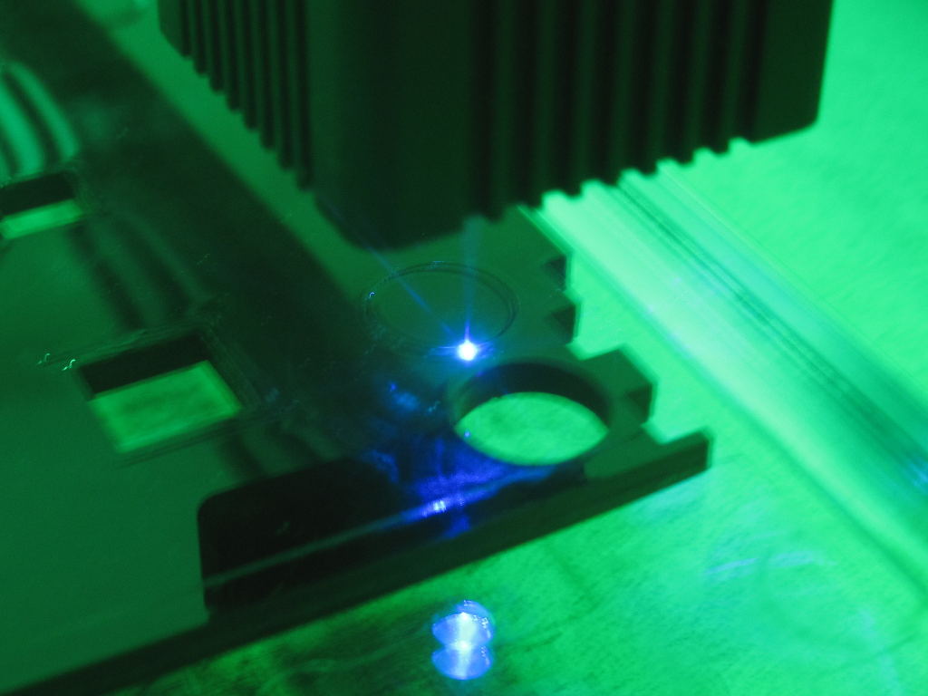
There is a small (and noisy) fan at the top of the 2.5W laser module, but it's made only to keep the laser module cool, and it doesn't blow strong enough to even disturb the smoke in the beam, as can be seen below while cutting some wood:
I first tried to place a battery-powered flat fan directly on the glass close to where the laser was working. This proved to work pretty well as long as the laser was no more than a few centimeters away from the fan, and it was not very convenient to move the fan to follow the laser beam:
Using a much larger fan worked better but was not convenient and quite noisy. It also had the undesirable effect of blowing some freshly cut light parts and sometimes moving them under the beam, causing some other areas not to be totally cut. So I tried to attach a small and light PC fan to the module to let it move along with the module:
This first experiment was not fantastic, to say the least... The air flow from the fan barely reached the surface, it needed to exhaust much closer to where the beam touches the material, hence this second assembly:
I started by stealing the 12V power directly from the original fan's pins on the board above but finally found it easier to solder a JST-XH 2-pin connector beneath the 3-pin one to take the 12V from there:
This actually is the one that gives me the best result. It does have one downside though: when cutting very light materials like thin cardboard, it tends to make the finished pieces fly over the place even though it doesn't blow strongly. And sometimes such pieces either need an internal cut (one more reason for etching from inner to outer), or they can deposit a few centimeters away on a place that was supposed to be cut, which is more problematic. I found that catching them with a piece of paper tape without stopping the work is easy enough not to care too much about this issue.
I tried a completely different approach by sucking the smoke instead of blowing it, using a small pump and a very soft silicone tube ending in water inside a jar. Long story short: it doesn't work, the suction is too weak. While the tube can stick to your finger, the flow is too small to collect the smoke from a few centimeters around. Maybe it would work with a stronger sucker, but it would also make too many bubbles in the water and would also suck the water out of the jar:
Motor driver replacement
During the first tests, I noticed that the motors were lacking a bit of resolution and that when the laser beam was very thin, some parts could be missed:
I've read on various forums about the
SilentStepper family of drivers which was supposed to render 3D printer motors totally silent and to significantly improve their accuracy by taking into account the amount of energy sent into the motor's coils and not just the ON/OFF time. Given that these ones are designed as drop-in replacements for the A4988 that my board is using, I thought about trying them. Most of these modules are programmable but I didn't want to go into this, so I picked the 2209 which supports 1.7A, doesn't require a heat sink with my motors, and defaults to 32 microsteps like the A4988. I just cut the unused programming pins and replaced existing modules:
The first thing I noticed was that the motors would go backwards. I just had to change the direction mask on my GRBL config for both axis (X=bit0, Y=bit1):
Grbl 1.1h ['$' for help]
$3=3
Once fixed, the positions and distances were working as before. However I was absolutely impressed by the total silence when the motors move. You don't hear them anymore at all, sometimes you can believe that etching is finished and you really have to look at the bream to be sure whether they're moving or not.
The second gain I got from this is that horizontal lines are evenly spread all over the distance. This is very important for raster images because before some lines would be left and others could be etched twice by being too close. Now the steps are perfectly regular. I tried to move the axis by sending various commands. The board is configured for 80 steps per millimeter, so we're supposed to be able to move by steps of 0.0125 mm. To be honest, I'm unable to say whether or not the motors move when I ask them to move this little, and it looks like when repeating the operations the motors move smoothly.
The third gain is that when moving fast we still keep some precision. I noticed in the past that when moving too fast I could sometimes fail a piece, because the laser head would miss a few millimeters on a large move. This has never ever happened anymore with these drivers. So they're really worth the money.
Enabling "laser mode" for raster images
The first time I tried to engrave a raster image (i.e. a bitmap image in black and white or with levels of gray), the result was awful. The motors would start and stop for every pixel with a different darkness level. It used to take a lot of time, to heat up the X axis motor, and to make burn spots at the beginning of each new segment of a same color.
I then thought "why not modify GRBL not to stop?". I just figured that it had already been implemented in version 1.1 under the term "laser mode". My engraver came with version 0.9, requiring an upgrade. I was a bit scared by horror stories on the net about some of the arduino-compatible modules there employing fake ATMEGA328P chips and not supporting being relfashed. I wasn't sure whether mine was affected or not:
In doubt, I ordered a small bunch of extra Arduino Nano compatible boards to flash the new version on. The problem I had with the Arduino Nano board is that it came with a Mini-USB connector while I mostly had Micro-USB cables. So I also tried my luck with a
RobotDyn NANO V3 board, which comes with micro-USB and a good voltage regulator, but which is also much thicker due to the crystals and the ISP connector, preventing me from closing the cover:
I flashed the
latest GRBL image (1.1h then) to the new device, and could start some tests. After about one week I decided that I wouldn't revert to version 0.9, so I decided to try my luck by flashing the original module that came with the engraver, and it worked. This allowed me to reinstall the acrylic cover on the controller board.
Laser mode is enabled by setting variable $32 to 1:
Grbl 1.1h ['$' for help]
$32=1
In this mode, the M3 command turns the laser on at a fixed power level, while M4 turns it on at a power level relative to the motor's speed during acceleration, to avoid burns. And more importantly, the motors do not stop if you don't send a new M3/M4 command while changing the spindle ratio. This means that you can produce very compact GCODE code using series of G1Sxxx commands describing segments of different intensities. This makes the laser go left to right and right to left and engrave line after line, exactly like an inkjet printer. Furthermore, G0 (travel) automatically turns the beam off so you can even optimize the printing using a fast traveling over white areas. It's worth noting that the X axis motor tends to heat up after a while but it remains OK. The resulting quality is extremely good. However it depends a lot on the material and on the software used.
I noticed that I often had to manually edit the output raster files to remove extra M3 or M4 commands placed there so that there's only one in the file.
I was finally fed up with constantly editing the files and started to write a
GCODE fixup script. Over time it grew into a full-featured GCODE manipulation tool that allows me to also adjust offsets, intensity, gamma, feed rate and even reverse an image. With a bit of experimentation it becomes convenient to figure the right parameters to apply to an incoming image to make it print exactly as desired on various materials (e.g. have shades on wood without burning), as can be shown here with this well-known Relativity drawing from MC Escher that I engraved on white 5mm thick plywood (which was then cut in 6 passes at 240mm/min):
In order not to burn too much material for testing, I figured it would be nice to be able to emulate the behavior of some materials and represent the expected result on screen. That led me to write the
laser-preview utility. It takes a GCODE on input and produces a PNG file based on some parameters (width, height, and diffusion ratio into nearby places). It's not that good and I'd need to redo it differently to improve the modeling of the physics of the material so that we could take into account the variations of reflection at various depths and the fact that some materials melt and that their absorption or diffusion changes with the phase change. But once you get used to validating the output on it for a given material, it does save some time and some material, which is already great.
The manipulations required to do all this and to change settings were quite long and painful, so I decided to write a
PNG to GCODE converter which does what it says, it takes a PNG on input, a resolution and some argument such as fixed size, cropping on each side, setting the spindle speed and feed rate, setting the number of passes, quantizing the values, normalizing intensity and applying some gamma/soften factors. The argument are placed in the output GCODE file so that it's easy to try again changing one parameter.
This significantly eased experimentation with new materials. For example with it I managed to print this sketch of me by
Frank Tizzoni on a painted metal business card (full one on the left, close-up on one part on the right) :
This was printed with a resolution of 200 microns. Experimentation shows that it's better to use a slightly larger step than the beam width (which was about 180 microns here). It's the best way to avoid over-burning some areas, this results in thin ~20 microns wide black lines that are barely visible. Achieving this requires a very fine focus adjustment, and burning a few cards with fine patterns. A macro close-up with a ruler (0 to 1 centimeter) is provided below showing this:

<

The card above was made using the "NEJE 20W" laser module, which has a much larger beam than the original EleksMaker one, but which is more powerful, and thus engraves faster. For raster mode, there is a sweet spot to find between fine level of detail and engraving speed. For example, engraving a large logo on wood or plastic wouldn't need this level of detail and would benefit from having fast passes. Engraving on very smooth and shiny paint like above achieves and extremely fine level of detail and definitely benefits from a smaller dot, even if that means using a less powerful module at a smaller speed. The card above is 5x7 centimeters and took roughly 40 minutes to engrave. With a finer dot, using a resolution of 100 microns, it would require twice as many lines, hence would take twice as much time at the same power level, or 3-4 times more with a less powerful module.
Trying a new laser module: NEJE 20W
I found a very appealing laser module that was easily adaptable to this engraver, it's the
NEJE 20W module. The module is well documented and easy to attach since it's the same width as the original one (30mm).
However, while initially advertised as 20W, it's "only" 5.5W optical power (the datasheet was since updated to reflect this). Despite this, it's still very powerful. Its fan blows inside and the hot air exhaust is close to the lens, resulting in it automatically blowing the smoke out of the engraving area. This is way better than what I've done to date with my other fan experiments.
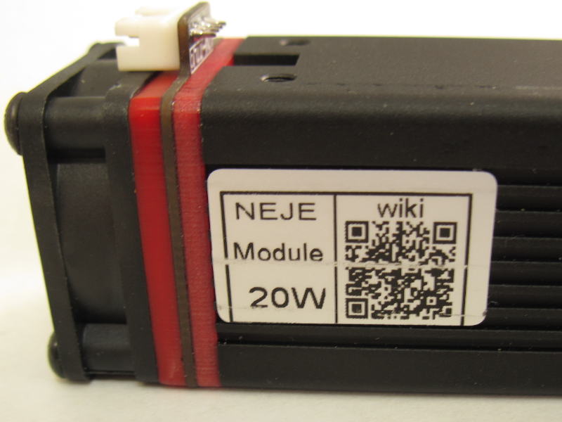
I initially had difficulties finding the connector's pinout until I figured it's printed on the solder side:
It uses a JST-PH 2mm 4 pin connector, and is provided with a cable that can be cut if needed. The main thing I've been missing on it initially was the alignment button which enables it at very low power to see a harmless dot. I figured that most other modules would suffer from the same limitation, so I decided to address this by creating the
laserdot project (board + code).
The principle of this tiny module is to use a micro-controller (ATTINY13A here) to detect the pulse from the laser controller, and send a very faint one when there is none for more than a few milliseconds. This ensures that the beam is never totally off, and ends up being even more convenient than the EleksMaker module with the button since there's no risk to start with the switch on the wrong position. The module was made so as to also serve as a connector adapter, so on one side it uses the NEJE 4-pin connector and on the other side it uses the EleksMaker connector.
Once you have the ability to work with a faint beam, it becomes obvious there's an issue with this one. It's extremely wide. It's not a dot but rather a line roughly 10 times as long as it's large. Plus it's oblique, making it even harder to use in the least problematic direction.
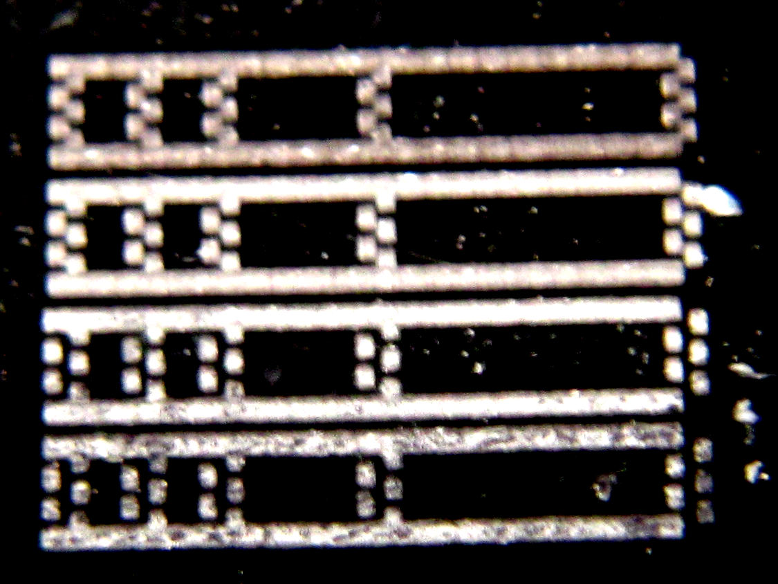
The photos below were taken through the protection goggles with the beam sent over a ruler composed of chip footprints. The beam length was roughly 3 cm. The first one shows the beam is roughly 0.8mm x 0.1mm. With the ruler aligned to the beam direction it's easier to measure it.
This means that even at 1 cm, which is very close, the beam will still be 0.25mm wide. The problem with very short distances like this is that the smoke directly enters the lens and risks to damage it.
At 5cm distance the beam is very wide and unusable for anything requiring a bit of precision:
I sent the beam to a wall to compare the EleksMaker 2.5W module on the left and the NEJE 20W (5.5W) module on the right:
As can be seen, most of the energy is packed into an almost square area with the 2.5W one, while it's on a 10x1 area on the 5.5W one.
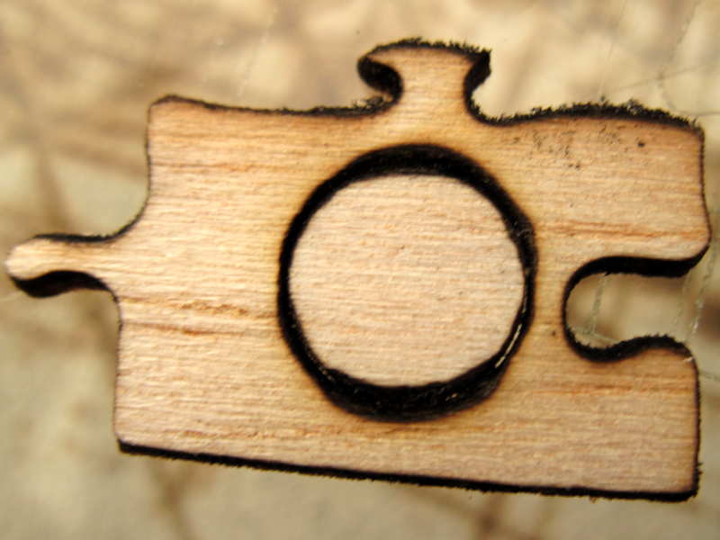
It's also visible that the very wide aspect-ratio beam makes it impossible to use it to cut anything small, because some directions are cut wider than others, as can be seen below trying to cut small 1cm circles:
I found that it is slower at cutting cardboard than the original laser module, because by using a much larger beam, a lot of energy is wasted. In fact cardboard can be cut with a very thin dot, which the original 2.5W module easily achieves faster.
It is possible to narrow the beam further by putting the piece to cut closer to the lens (1 cm), but as mentioned above, the smoke enters the lens and deposits dust on the glass that needs to be cleaned up regularly using isopropyl alcohol. The effect of smoke on the lens is that the spot becomes blurry:
There is another issue when trying to cut thick material, which is that the beam diverges much faster and is either unable to cut thick material at all, or manages to do it but with an oblique form, and as such it cannot be used to cut wood to make tabbed laser boxes for example:
I noticed that it has become increasingly difficult to cut acrylic with this laser. Initially I wondered what could have been the reason, maybe I initially managed to very finely adjust it and cannot do it anymore. But I came upon
NEJE's Wiki for this module which explicitly mentions that modules like mine bought before last October could be subject to aging and attenuation, so I suspect it might be the issue I'm seeing. I tried to contact them but for now got no response. I'll see.
With the default lens, this laser can still cut quite fast and engrave painted metal at 1cm focus, but the cut remains quite large, even when cutting balsa wood like below:
And the large spot combined with the high power tends to inevitably make balsa catch fire. I never managed to perform a small cut of a 3D puzzle with this one. The lower the speed, the higher the risk it will catch fire. The larger the spot, the higher the risk as well. For this reason it's extremely important never to leave it cut with nobody watching, as can be seen on the failure below! I though about wetting the wood a little bit, but that doesn't work, it bends a lot, which is understandable given the nature of the wood cells as seen above in the close-up.
Also it is important not to use too short a focus to cut wood, as the beam will have a cone shape and be very large at the top, burning wood a lot:
The high power from this laser module had a side effect on my operations, which is that it managed to engrave the glass support. It's pretty visible below with the puzzle being engrave in the glass. It's still uncertain how the laser should be adjusted to do this, it seems that it only happens when there is some matter above. So probably that the concentrated light heats the smoke above the glass at a very high temperature at which the glass melts. This would deserve more experiments, because it might be useful to cut glasses to precise dimensions, for example by first painting it or just placing some duct tape on it.
Similarly it engraves brick. What's fun is that it melts and crystalises the matter beneath the surface, making it look like quartz, which thus becomes transparent and stops absorbing light. So only the first millimeter melts but it doesn't evolve at all anymore past this point, regardless of the number of extra passes:
Trying new lenses
The extra power available in the NEJE module is quite appreciable but the loss of precision is a real issue for some work. Since a lot of lenses are available on the net at different prices, I accepted to invest in a few of them to run more experiments.
First, it was visible that a number of them are not suitable due to too large or too short a focus. The one from the 2.5W module for example is not suitable for the NEJE module.
I then tried a
single-element lens. I found that the spot looked small but it didn't seem to burn very well. Then I understood. It needs not to be inserted deep enough, and for its small internal aperture, a significant part of the beam is wasted on the metal parts inside. Thus what appears as a small spot is in fact just a small part of the emitted light.
I found many references to
3-element lenses, so I tried two of them (they ended up being the same so a single one ought to have been enough). These lenses have a slightly longer focus than the original one, allowing to get approximately the same spot size at a slightly larger distance. Here at 16mm I get a spot of about 0.2mm matching what I used to get at 1cm:
Interestingly the simple lens that's found in Aixys modules gives reasonably good results, in that the spot is quite sharp at a long distance (29mm) even if not very small (~0.25mm):
But it still cannot cut acrylic after several passes, and it's visible that the beam is too wide:
Overall even for cutting cardboard it's still not enough, a single pass at 400mm/mn doesn't cut while it does with the original 2.5W module:
Since it's very difficult to adjust lenses at a short focus, I figured that it's easier to invest time adjusting them at a well-defined distance and use a wedge to adjust the module on top of the piece to etch instead:
However this requires that the lens' thread is firmly secured, which is not often the case. I found that the best solution for this is to put some Teflon tape around it. It even makes it much less sensitive to vibrations and should improve overall quality:
The difference can be important, as can be seen below trying to engrave 5mm circles (the circles borders are distant 0.5mm each). The one on the right was made with visual alignment. The one on the left was made after many attempts were made on top of a 11mm wedge.
I found the
DTR-G8 lens which seems to get a lot of good reviews. It's quite more expensive than others ($34 shipping included) but the results are actually impressive. The spot is by far the thinnest obtained from this laser module, around 0.1mm wide at 11mm, which is how the circles above were etched. The lens has a wide internal aperture and collects a very large part of the beam:
And it delivers a very thin and sharp spot (the pads have a 0.4mm pitch, are 0.25mm wide and spaced by 0.15mm):
Making your own module
I tried to reuse an old module I built myself from a kit. It's made of a 1W blue laser diode, a PWM driver and a heatsink+collimator lens.
It required some adaptations to fit into the actual support, but nothing too difficult:
This diode being less powerful, it's more compact and is actually what managed to deliver the thinnest spot of all modules. It is visible on this test on a PCB's top side with the concentric circles where the cut is much sharper and around 50 microns wide only from 6 centimeters (the rest around is burnt):
This module doesn't have room for a fan, though it doesn't heat too much thus it seems it would stand working like this. However it also means that the smoke is not blown and hinders the work. It really requires at least a lateral fan on the work piece to blow the smoke away.
I suspect it would constitute the best solution for very fine PCBs, working at moderate speed, and would require less adjusting time than the other ones.
Printing on cylinders
It is possible to print on cylinders such as toilet paper rolls by connecting a stepping motor to the Y axis connector. It requires adjusting the Y scale to accommodate for the cylinder size and to firmly attach the piece to be engraved to the motor:
I thought about improving this with rotating axis to place anything on them, and while looking for mechanical parts to build such a device I discovered that some vendors were already making some such inexpensive ones like
Eleksmaker's Eleksrotate so I decided not to waste my time hacking with mechanics since I've never been good at this.
Final words
That's already quite a long article, showing the extent of what is possible to do with such a fun device. I'm still a bit disappointed by the NEJE 20W module because while more powerful it has a very impractical spot shape and seems mostly useless for my use cases. And with careful adjustments the original Eleksmaker module remains the most versatile one.
Every user should absolutely upgrade to GRBL version 1.1 to benefit from the laser mode. I'd like to modify the code to integrate the low power on for centering, which will allow me to drop the laserdot module.
I also found during tests that printing on top of PCBs works very well and could actually be used to print the components references. That's probably something for a future article.