Introduction
ALIX is the name of a nice motherboard family designed by PC Engines to build small fanless, quiet, cheap and still powerful servers. Those motherboards are sold without battery for the RTC clock, so as soon as the power is lost, the clock is lost and at next boot, the clock will be set to Jan 1st 2000.When working on packaging a Linux distribution for these motherboards, it is normal to encounter various boot errors and to have to power cycle the board tens of times a day. After a while, having to set the clock manually becomes irritating, and at least being able to keep it running for a few minutes would be very useful.
Solution
Since the RTC clock is known to run from very low power, I decided to experiment with a few capacitors with pretty interesting results. A 1000µF charged at 3V3 and connected to the 3V battery input is able to keep the clock running for about 30 minutes. This is more than enough for most of the power cycles I have to run through.This capacitor will have to be charged during operation. Since the power supply does not charge the battery, a diode will have to be connected between the 3V3 power line and the capacitor. Unfortunately, a silicon diode shows an important voltage drop (0V6) which considerably reduces the efficiency of the solution.
Experiments with a germanium diode with a lower drop (0V3) connected to the 3V3 power line charges the capacitor to 3V. Another test with a silicon diode connected to the 5V power line charges the capacitor to 4V4, providing slightly increase longevity.
I finally decided that both of my 2C3 motherboards used as servers will have a 1000µF capacitor charged at 3V through a Ge diode, to power the clock for about 30 minutes. The 3C2 board which I carry everywhere with me for development and experimentation purposes will have a bigger 0.1F capacitor charged at 4V4, managing to keep the clock running for two days.
Installation on the 2C3 motherboard
Locate the power lines
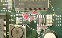
On the 2C3 motherboard, it is very easy to locate the power lines. The 3V3 is available on C172, very close to the battery connector, and a small capacitor already brings the ground even closer, basically at the distance of a capacitor, so this will be quite helpful. Click on the image on the right to get a full size view.Identify the connection points
Here is a close-up of the work area enlightened above. The view has been rotated for easier identification. The components will be connected as indicated on the image. Click on the image to get a full size view. First, prepare the terminals with some solder. Put a drop of solder on the pin of C172 facing U12, as the diode will be connected there. Do the same on the "-" pin of C26, which is also facing U12 ; the capacitor will be connected there.Prepare the components
 |  |
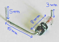
Then, get a 1000µF 6V3 radial capacitor, cut its pins to 8mm, and bend the positive terminal perpendicularly for horizontal soldering (not shown on the image).
Install the diode

Solder the diode first. Its anode connects to C172, on the pin facing U12, and the cathode connects to the battery's connector, in the hole designated as BT1+ (in fact it's the + terminal of battery BT1). It is important to leave the cathode exposed (not isolated), because the positive pin of the capacitor will be soldered directly on it.
Install the capacitor
Solder the negative pin of the capacitor to the negative pin of C26. Orientate it so that the positive pin joins the diode's cathode on BT1+.

Installation on the 3C2 motherboard
Install the diode

Here on this photo, the +5V is taken from the left pin of C23. The diode is not easily identifiable, it is the small black plastic thing located just above the R20 printing. Its anode is connected to the +5V via the yellow wire, and its cathode is connected to the BT1+ pin on the board.
Install the capacitor
 The capacitor is what is sometimes called a "SuperCap". Its capacity is 0.1F, or 100000µF, which is 100 times the capacity of the ones used on the 2C3 motherboards. It is slightly bigger and there was no easy place to install it. I finally decided to stick it on top of the CS5536 (U11) which is approximately the same size and is perfectly flat.
Another advantage of this location is that the power line from the BT1+pin enters the CS5536 via the C38 capacitor, which provides an easy access to both the positive and negative terminals. Also, it is important to note that BT1+ is not directly connected to C38, but passes through R20 first, a 47 ohm resistor.
In the end, it is a good thing that there is a small resistor between the power supply and this capacitor. It has a very big capacity and a small internal resistance, and having R20in the path ensures that it does not pull too much power through the diode at start-up.
Connect the capacitor to C38 as on the image on the right, with the negative pin to the left ot C38 and the positive pin on the right. That's all, you're done.
Various links
- http://pcengines.ch/ : PC Engines's web site.
- http://pcengines.ch/alix.htm : the ALIX motherboards at PC Engines.
- http://www.st.com/stonline/products/literature/an/5226.htm : an interesting application note for SuperCaps and time-keeping I found while writing this article.


