2019-01-20

Making a simple sunrise alarm clock

Purpose

I like to get up early to have more time to work and design in a quiet place. (Well, I have a joke that lazy people get up earlier to have more time to do nothing). I noticed that in summer it's easy to wake up with the first sun rays, but in winter it's more difficult. And in order to optimize your sleep cycles you don't want to be woken up by a noisy alarm clock. So I've long wanted to build my own progressive lighting with a programmable clock.

Possible components

The controller


Years ago I thought about building an alarm clock the old way, with a clock derived from the 50Hz on the mains, using an AVR microcontroller, with 7-segment digits. It would require an interface to set the clock up, etc.

Then when playing with my first ESP8266 I quickly managed to implement a remote controlled power plug and figured it wouldn't be hard to use this to make my alarm clock, and that it would simply retrieve the current time from a regular NTP server. It started to sound good.

The lights


I first thought about using an halogen lamp and a triac, but I didn't like the idea of letting such a fire igniter run by itself if I'm not at home, thus I started to experiment a lot with high power LEDs (1, 10, 50, 100W). High power LEDs are difficult to cool due to the high power density which requires a massive heat sink. My largest fan-less one is a 100W one that I limit to 45W. Also I figured that having such a huge power directly in your face is not the thing that makes you want to get up the most.

I then discovered LED strips. These ones are very convenient. The power is spread over a long length and thus a large surface. They don't need to be as powerful as compact LEDs because they already cover a long range, and they are easier to stare at.

Final choice

I opted for an ESP8285 made of a PSF-B85 board. It's extremely compact and has everything I needed, plus it's supported by the NodeMCU firmware :


For the display, instead of starting with 7-segment LED digits, I wanted to experiment with some I2C OLED displays which are also supported by the firmware. I found very cheap 128x32 graphics displays like this one. If I had to pick a new one though, I'd pick a larger one as this one is very small.

For the lights, I've opted for white LED strips. It is important not to pick the cheapest ones though. I discovered that some are not adhesive, and some expectedly adhesive ones have a very poor quality adhesive which quickly dries on your shelf and doesn't stick anymore when you unroll it. Also, some come with incorrectly soldered LEDs or even some with reverse polarity. I had to fix mine by hand, about 5% of the LEDs wouldn't turn on due to poor soldering. Preferably pick one from a vendor with a very good reputation, and stay away from misleading or confusing descriptions which often indicate lack of care for quality.

This time I needed to put this into an enclosure with buttons. I had some (very) old PVC enclosures made for MIDI adapters which were of the appropriate size, so I could start with this.

Design

PWM driver

Controlling a LED for progressive lighting requires some PWM. The NodeMCU firmware running on the device supports emitting a PWM signal on one pin. But I needed to amplify this PWM signal to drive tens of Watts.
I restarted from the design I came up with for my high power tv-b-gone, and adapted it, resulting in this :


Planning for supporting high power, I changed the MOSFET for a larger one at the last minute. The diagram above shows an IRF7313 (dual FET) but I preferred to pick an IRLR3715 which stands higher currents pulses and better spreads heat into the PCB (supports 54A/71W vs 6.5A/2W).

Programming

This time I didn't want to have to solder wires to reflash the device if things went wrong, so I decided to start with an easy solution. I implemented the adapter I designed here with a 6-pin connector so that I could simply attach an FTDI adapter to flash the board. In addition, among the two buttons, the first one will be used to switch to recovery mode during boot in case things go wrong. This was used quite a number of times during development :-)

Voltage regulation

Like most ESP boards, this one requires a regulated 3V input. I preferred to use a switching DC-DC module instead of using a linear regulator, because the linear regulator would heat a lot by dissipating the difference between 12V and 3V.

PCB

I had everything ready to start designing the PCB. Only add one decoupling capacitor, a power connector, another connector for the LED strip, and the two buttons. The DC-DC module will be external for simplicity. As usual I did it the old way with the pen since it remains the fastest method :


Construction

Time to throw the PCB into the etching bath. I should document my alternating etcher by the way :


Ten minutes later, I picked it out of the bath, cleaned it and drilled it. The result is quite good :


Let's place the SMD component first. Below two versions, one raw, and another one with all the signals annotated :


Then place the PTH components and connectors :


Connecting to the PSF-B85 is not easy due to the 1.27mm pitch between the pins. The solution I turned to was to use some 1.27mm pitch floppy drive cables, allowing me to easily connect pins and still have long enough wires to go to the various places on the board. The result doesn't look pretty but it allows to move the board around to check signals and to replace it if needed :


Programming

I've reused the iot-core framework I developed on top of NodeMCU, and had to iterate several times using NodeMCU-build because my code ended up using lots of memory and I had to remove lots of unused modules to save memory.

Among the unexpected "innovations" there, I had to implement several programs depending on the displayed screen. NodeMCU can reclaim memory of an unused program so the final program is very similar to what you're used to do when using lots of UNIX commands at a shell. The program is like a shell which launches programs. Switching to another program is fast enough so you don't notice. All the code is available here. Feel free to duplicate it and use it.

I just had to connect my FTDI adapter to the purposely installed 6-pin connector and the programming was trivial :


One nice thing of keeping the voltage regulator external is that during development, the FTDI adapter is sufficient to power the board so you have total control over it. Keeping the leftmost button pressed during boot is enough to drop to the Lua interpreter shell (this is handled by the iot-core framework which refrains from loading the application in this case).

I implemented a few simple functions to draw large 7-segment digits on the OLED display. These ones are explained in the source code. The result is quite good (the differences in intensity are  caused by the refreshing) :


The buttons are used like this :
  • button 1 : switch between multiple light modes (on/off/rise/fall ...)
  • button 2 : switch between multiple screens (big digits, status, alarm setting)
When setting the alarm time, an underscore is placed below the digit being edited. Button 1 increments this digit and button 2 switches to the next digit, so setting 3:40 above roughly requires 7 + 4 button pressures. The first digit can be turned to "-1" to disable the alarm.

The lighting modes are very simple : by default, the output is in mode 0 which is off. Once in mode 1, the PWM output slowly rises from 0 to 100% over one minute, then it reaches mode 2 which is always on. Mode 3 falls from current value to 0. This one is convenient to leave the room after pressing the button. I had to change from linear to quadratic progression, because the eye doesn't react linearly to the LED intensity, and when used linearly you feel like there's little difference between half-lit and full-lit, so it was too fast at the beginning.

A completely useless feature I implemented was to indicate the day of week on the left of the hour and on the status screen between parenthesis. But I figured I never used it. I thought I would make the alarm programmable by day of week but there's no need for this, it's so easy to adjust twice a week that it's not worth the pain of making the configuration more complex :


Final assembly

The PCB was placed inside the plastic enclosure, with some foam to plug the rear holes.


The finally assembled box looks like this :


For the LED strips, I've placed two 3-meters wide ones in parallel and connected them using some thin telephone wire. Since the ceiling is oblique in my room, I thought it was the perfect place to install it so that it doesn't send the light into the face while still casting it strong enough to wake up :


Results and lessons learned

It has been running flawlessly for more than one year. In that regard the NodeMCU firmware is quite stable. I faced some stability issues with the first PSF-B85 module I used. The device would randomly reset several times a day and sometimes switch to the wrong baud rate. I spent a lot of time trying to debug this and improving power decoupling and pull-ups, to come to the conclusion that the device was faulty. I replaced it with another one and all issues disappeared.

The amount of RAM is too small for such applications to remain convenient to implement. What I like with NodeMCU is that you have a shell so you can debug and develop live without having to implement everything in your code, rebuild and upload. But it also means that files are compiled on the device before being processed. This takes a lot of RAM. The solution consists in saving them pre-compiled but it's not possible anymore once the application is loaded. It causes me issues twice a year when changing the daylight savings time. For this I have to connect over telnet, edit the configuration file, save it, reboot in safe mode by holding the button, recompile the config file, and reboot. It's quite of a pain.

I thought about re-implementing all of it in C using a different framework but it would take quite some time just to save half an hour twice a year... Not very tempting. The best long-term option would be to switch to the ESP32 which has way more RAM, but the NodeMCU kit is still in development for this device so I don't know if it works or not by now.

The OLED display is not great. First, the MCU doesn't have enough memory to draw on the screen at once, so it has to use pages and to draw the same image 4 times with a mask and only send one page at a time. Not only this is slow to compute, but it also requires quite some I2C bandwidth. Each screen change takes slightly less than half a second. It's annoying when changing the alarm time. The digits are small and very bright. At night it can be slightly blinding and possibly not always very readable for people who wear glasses. Larger red digits would be better in and less aggressive the end.
Also the OLED display wears quickly. The areas having the most segments lit are now fainter than the other ones.

The LED strip is too white ("cold" in LED vocabulary). It's a 6500K white. I hesitated with a 3200K that I already had and which I found too yellow. I think a good approach is to mix two of them. I'd need a bit more power as well. Right now the strips draw between 15 and 20W. I should go to 25-30W for a better effect

Another surprising point is that one LED is constantly lit despite the output showing zero volt. The reason is voltage leaking by capacitive coupling between the power supply and the wall! The lowest voltage LED is the one which turns on. During day it's not visible but at night it is. Installing a 1K resistor in parallel to the strip is enough to turn it off, but it would dissipate some power. I really don't care so I didn't fix it.

The LED still turns too fast from 0 to 100%, especially from 0 to, say, 10%. I think that making it more progressive over 10 minutes would be better. Ideally some experiments should be made with RGB lights such as WS2812B to better mimmick the sun's colors in the sky :
  • start reddish for a few minutes
  • progressively add the green component to make it yellow
  • then add the blue component to turn white
I'm not sure how much power I can pull from a WS2812B strip though, since it works on 5V and it will not accept well to take many amps. I've also read some stories about these devices being sensitive to interference on long distances. This can be amplified by the high current required to have enough power to properly light the room.

I found it convenient to keep the light on for 30 minutes. It starts 20 minutes before the buzzer-based alarm, and almost always manages to wake me up so that I can stop the alarm before it rings. Thus it seems that with this amount of light, I need 20 minutes to detect the light (possibly finish a sleep cycle).

Interestingly such devices increase the probability that you wake up at the end of a cycle, and help you measure the length of your sleep cycles. You need to keep in mind to note the first hour you observe when waking up. I could measure mine to be multiples of 100 minutes (well more precisely 97 to 99 in fact), which is convenient to count since 300 minutes are 5 hours. I managed several times to wake up easily after 200 minutes (3h20). What I don't know yet is if in reality these are multiples of 50 minutes. I'm not yet sure about the effectiveness of 4h10 (250 minutes), since around this duration my few experiments have shown irregular results. Anyway I know it would not be enough for me over the long term.

Overall my sleep is much better and I'm much fresher in the morning. No more headaches when sleep is suddenly interrupted by the buzzer. I long thought I needed 6 hours but I feel way better with 5 hours with a soft wake up like this than with 6 hours using the buzzer previously. It once stopped working (poor wiring connection on the DC-DC board) and repairing it went very high on my priority list!

Ideally I should build a new and better version of this device, but I wouldn't value the improvements that much for the time required to make another one. So let's wait for it to die first :-)

2019-01-06

Build farm, version 3 (2018)

[this is a follow-up to this article on version 2 of the build farm]

Background

The MiQi-based build farms had been running very well both at home and at work over the last 2 years. I noticed that some very large files in haproxy totally dominate the build time (notably cfgparse.c), and can keep a core busy from the beginning to the end of the build. It was a signal that this file needed to be split into pieces, but it also made me start to study possibly faster CPUs, including some big.LITTLE combinations.

New CPUs

I had been lurking for some time on the fresh new Rockchip RK3399 SoC, featuring 2 Cortex A72 and 4 Cortex A53. These devices were presented either under the form of a quite expensive T-Firefly development board or as various types of TV set-top-boxes. I found a moderately affordable one, the H96 Max. It's easy to get confused since all their devices are called "H96 something" or "H96 max something". Here it's purely "H96 Max", no "pro" nor "x2" nor "h2", like this one. Getting Linux to work on this one proved to be quite a bit of a pain at first. I had to make my own USB A-A cables to access the flash, and solder wires inside to access the console port, then try many different images to find a bootable one (I don't even remember which one worked in the end).


The RK3399 inside us supposed to run at 2.0 GHz for the big cores and 1.5 GHz for the little ones. As usual with this type of devices this is a lie, it's only 1.8 GHz for the big ones and 1.4 for the little ones.

Despite this, the performance was attractive as it reaches the same performance level as the overclocked MiQi. It's also visible in this performance report that the 4 little cores deliver together the same performance as the 2 big ones, meaning that the 2 large cores at 1.8 GHz have roughly the same performance as 2 overclocked cores on the MiQi.


But if the larger files landed on the A53 cores, then it was a disaster, with the build taking too much time. At 1.4 GHz, an A53 takes roughly twice the time to build a file than an A17 at 2.0 GHz. So this device was overall faster but could be up to twice as slow depending on the scheduling. I continued to explore it a little bit.

I later figured that there was a memory controller tuning issue with this board. It runs on LPDDR4 but is configured by default with low performance settings like 200 MHz or so! Also there is some arbitration to access the L3 cache between the little and big cores, and the little cores get a very low bandwidth, which explains a number of things. By then I didn't figure how to work around all these limitations.

Then came the NanoPi Fire-3. It's exactly the board I had been waiting for for 2 years. It features 8 A53 cores on a very small size, and there is no wasted component on it. I bought one, found the CPU was designed to be 1.6 GHz, thus I set it to 1.6 after adjusting the thermal throttling levels, and found this board to be a much better performer than the A53s in the RK3399. However, while this board probably holds the performance-to-price award, it's not faster than the MiQi so I didn't want to "upgrade" the build farm with it, it wouldn't make sense.

After HardKernel released a new version of their Odroid boards called the MC1, specifically designed for clusters, I decided to give it a try as it was perfectly matching my needs. And the Cortex A15 was supposedly fast, and running at 2 GHz there. I found that while the CPU is indeed pretty fast, its memory performance was one third of the MiQi's, which is not surprising given that tha Cortex A17's main improvement over the A15 was supposed to be a completely revamped memory controller. The build time heavily depends on memory performance,  so the board was only as fast as the MiQi with stock settings. I would have built the farm out of it if I hadn't had the MiQis though, as it's much less hassle to cool it down.

The NanoPi Fire-3 experience made me realize that the Cortex A53 wasn't that bad if it could be driven at a higher frequency and with a correct memory controller. The main problem is that it's often used in low-grade chips for which vendors are lying a lot regarding frequencies. I noticed the new Allwinner H6 supposedly running at 1.8 GHz, so I decided to order an Orange Pi One Plus featuring it. It indeed ran at this frequency, but the performance was a disaster, due to very poor memory performance.

A few days later, once at Haproxy Technologies we had assembled our new network benchmarking featuring many SolidRun MACCHIATObin boards, I couldn't resist the temptation to install my build tools on them for a test. And this board featuring four 2.0 GHz Cortex A72 cores was the first one to be faster than the MiQi at the same frequency. 20% faster to be precise. It's easier to cool and has the same number of cores. The board is much more expensive than the MiQi but this convinced me that the A72 could do the job.

Past the holidays period, FriendlyELEC issued their long awaited NanoPi-M4 board, which by then was the smallest and cheapest RK3399 based board. And it was perfectly designed, like many of their boards, with the CPU on the right side (the bottom) to ease cooling. It was the same price as a MiQi, but included the huge heat sink. Knowing that I would have everything I needed (docs, schematics, source code), I immediately ordered one. The result was quite good out of the box, the same as the stock MiQi. With proper tuning I found that the big cores would accept 2.2 GHz and the little ones 1.8 GHz, but not with the big at 2.2 at the same time.  It was OK with the little at 1.8 and the big at 2.0 though. These little cores are the most important ones for the build time in fact. And the new record of all times was easily broken here with 14.5s vs 17.6. It was even slightly faster than the MCbin. So now I knew what board I was going to order :-)

The new board

Slightly later than the NanoPi-M4 FriendlyELEC issued an even smaller and cheaper model, called NanoPi-Neo4. For only $45 you get this tiny board with these 6 powerful cores. I noticed that the board's layout easily allows to mount them vertically with all connectors on one side and the heat sink behind :

I soon saw they had a discount for the Black Friday period and after thinking a bit how to arrange them into a farm, I decided to order a bunch of them, 5 to be precise. But I was limited to two on the site! I asked them about this limitation and they very kindly offered me to participate to my build farm setup by offering me the 3 extra boards I needed. This was awesome! I remained very reasonable, with only the boards, an eMMC module to host the operating system, and the USB power cables because I know that just like with MiQi, their cables are of excellent quality. I didn't even take the heat sink because I had other plans ;-)

New build farm layout

The ability to stack multiple boards vertically as close as possible from each other was extremely appealing. I realized I would only need an L-shaped aluminum block to connect each board to a larger common heat sink. I spent some time looking at DIY stores and finally found what I was looking for : 5.2cm wide and 2mm thick aluminum corner :


Once sawed it perfectly fits :


Then I drilled the holes for the screws :


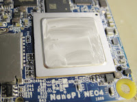
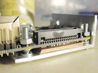
One issue remained : the SoC is thinner than the micro-SD card reader. I expected to directly put thermal paste on it but it will not touch the aluminum plate so I need a thermal pad :


I didn't want to use soft thermal pads since I know they are not very efficient. For a test, I started with some ceramic pads that I had :


The result was OK, the CPU was touching fine :


I assembled everything and I ran some tests with cpuburn to verify that it was OK (and it was) :


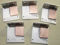
But my thermal pads were not all the same and I preferred to switch to copper pads later to better conduct the heat through the aluminum with less losses (copper having a lower thermal resistance than aluminum). For this I wanted the pads to be as large as possible. I sawed a 10cm wide 2mm thick copper plaque I had, into almost identical 3.2cm wide pieces, and polished them. Also, since the CPU is close to the edge of the board, the thermal pads need to have a notch on one corner so that the screw can pass.

It's a real pain to saw thick copper by the way, because it is ductile and doesn't stay perfectly flat when attacked with a saw. Next time I'll try with a thinner plate. From my measurements, 1mm should be way enough. But eventually I had my 5 copper thermal plates in place:


Finally it's starting to look like a build farm:


I found that the thickness of my thermal pads could be an issue for the board, because I didn't want to force too much on the screws but still I wanted the board to firmly press the CPU onto the pads. I opted for some form of soft fixation. For this I've cut some springs, placed them between two washers on a screw. This allows me to adjust each screw individually without risking to bend the board too much. This is important because you definitely want to use as little thermal paste as possible to make the best quality contact, and for this to be possible you need the CPU to firmly press on the pad :


Now all boards could finally be prepared, and the final shape starts to become visible :


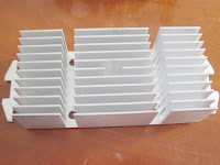
I needed to find a large enough heat sink to place behind without disassembling the previous farm which still works fine. I opted for and old Pentium2 heat sink which happens to be of the exact same width as the set of boards:


I figured that it would be pretty difficult to fix the boards using screws to this device. So instead I've used a large band of thermal tape, the same that I used with the MiQis. It's not perfect but it's good enough if you press firmly to attach the boards and cover all the surface with it:


The resulting assembly makes a nice compact block:


This new cluster is finally ready to replace the previous one in the home cluster:


Installation

I simply installed the default image from the FriendlyELEC wiki dedicated to this board. Since I already had the micro-SD to eMMC adapter, it was fairly straightforward to download the images and copy them there :


I had to disable a lot of the systemd related crap that eats CPU for nothing or wants to have fun with your nerves by being creative with your network setup, as well as disable graphics mode which eats memory for no reason in this specific use case :
# for i in gpsd ModemManager bluetooth dnsmasq systemd-resolved.service networkd-dispatcher.service; do
> systemctl disable $i; systemctl  stop $i
> done
# apt-get remove wpasupplicant
# apt-get remove lightdm

This way I could have my own network setup with static IP addresses, my own resolv.conf, and have better control over what is being done, without the fear that WiFi would suddenly turn on and expose the boards to the net for example...

I did a mistake you must not reproduce : I first installed one board and duplicated its flash to make the other ones. This resulted in all boards to have the same MAC address because it's U-Boot which randomizes the MAC address in its config upon first boot (which is quite convenient by the way).
I found where U-Boot's environment is stored and was able to destroy its checksum from the command line, getting a new random MAC address on next boot :

# dd bs=1 count=4 seek=$((0x3f8000)) of=/dev/mmcblk1 if=/dev/zero

My boards are named "neo4a" to "neo4e". Given that there's plenty of room on them (8 GB), I've installed several compilers for various target architectures and in different versions. The ones provided on kernel.org work almost out of the box there, there's only a symlink to add from libmpfr.so.4 to libmpfr.so.6. I've installed versions 6.4 and 7.3 for i386, x86_64, arm, aarch64. And I've standardized the names like this : <target>-<gccversion>-linux-gcc for ease of use and so that they could match similar names I use on my build machine while masquerading by distcc :

$ ls arm*
arm64-gcc-7.3.0-nolibc-aarch64-linux-gnu.tar.xz
arm64-gcc-7.3.0-nolibc-arm-linux-gnueabi.tar.xz
arm64-gcc-7.3.0-nolibc-i386-linux.tar.xz
arm64-gcc-7.3.0-nolibc-x86_64-linux.tar.xz
arm64-gcc-6.4.0-nolibc-aarch64-linux-gnu.tar.xz
arm64-gcc-6.4.0-nolibc-arm-linux-gnueabi.tar.xz
arm64-gcc-6.4.0-nolibc-i386-linux.tar.xz
arm64-gcc-6.4.0-nolibc-x86_64-linux.tar.xz

$ HOSTS=neo4{a..e}

$ for c in arm64-gcc-6.4.0-nolibc-*xz arm64-gcc-7.3.0-nolibc-*xz; do
> echo $c
> for h in $HOSTS; do
>   ssh $h "sudo tar -C /opt -Jxf -" < $c
> done
> done

$ for h in $HOSTS; do
>   ssh $h 'sudo ln -s libmpfr.so.6 /usr/lib/aarch64-linux-gnu/libmpfr.so.4'
> done

$ for h in $HOSTS; do
>   ssh $h 'for f in /opt/gcc-*-nolibc/*/bin/*-gcc; do v=${f#*gcc-};v=${v%%-*};v=${v//.}; n=${f##*/};sudo ln -sv $f /usr/local/bin/${n/-linux/-gcc$v-linux};done'
> done

$ sudo ln -s /usr/bin/gcc-7.3.0 /usr/local/bin/x86_64-gcc730-linux-gcc
$ ln -s /usr/local/bin/distcc /home/toolchains/x86_64-gcc730-linux-gcc
$ cd linux
$ make -j 60 CC=/home/toolchains/x86_64-gcc730-linux-gcc bzImage modules

Optimizations

I tried to push the CPUs to their limits and found that one of the boards didn't like to have its little cores run at 1.8 GHz, but was perfectly OK with 1.7. However it's OK with the big CPUs at 2.2. In the end, in order to ease maintenance, all boards have been configured to run at the same speed, 2.2 + 1.7, which I'm setting using this script (some kernel patches are required to get the extra frequencies, see below) :

# cat set-speed-neo4-1.sh 
echo 2 > /sys/kernel/debug/clk/sclk_ddrc/clk_enable_count
echo 928000000 > /sys/kernel/debug/clk/sclk_ddrc/clk_rate
echo 1 > /sys/devices/system/cpu/cpufreq/boost 
echo 1704000 > /sys/devices/system/cpu/cpufreq/policy0/scaling_max_freq
echo 2208000 > /sys/devices/system/cpu/cpufreq/policy4/scaling_max_freq
echo performance > /sys/devices/system/cpu/cpufreq/policy0/scaling_governor 
echo performance > /sys/devices/system/cpu/cpufreq/policy4/scaling_governor 
echo performance > /sys/devices/platform/dmc/devfreq/dmc/governor

I tried manually to increase the thermal thresholds to limit throttling with good success until I moved them into the DTS :

# cat set-temp.sh 
echo  85000 > /sys/class/thermal/thermal_zone0/trip_point_0_temp
echo 100000 > /sys/class/thermal/thermal_zone0/trip_point_1_temp
echo 115000 > /sys/class/thermal/thermal_zone0/trip_point_2_temp

Pushing the limits

In order to play with the board, you need to clone the board's kernel from FriendlyELEC's GitHub repository here. The branch to use is "nanopi4-linux". The procedure is described in the wiki here.

When you build the kernel using "make nanopi4-images", you'll get three device tree images in one single "resource.img" file. It is important not to try to build your images by hand and to use the appropriate make targets, as you absolutely want the device trees blobs to be appropriately named. Indeed, the boot loader looks for their respective names in the resource partition. Their names are as follows :
  • rk3399-nanopi4-rev00.dtb for the NanoPC-T4
  • rk3399-nanopi4-rev01.dtb for the NanoPi-M4
  • rk3399-nanopi4-rev04.dtb for the NanoPi-NEO4
It helps to know which one you are using, especially when you're not modifying the correct one and are wondering why the changes are ignored.

If you want to add new frequencies for your board, you have to modify the respective DTS. It is strongly recommended to only add them as "turbo-mode" entries, so that they are not picked by default unless the "boost" variable is set. This way the board can boot safe and only hang once you enable the new frequency. Example with this patch adding 1.6, 1.7 and 1.8 GHz operating points to the little cores :

diff --git a/arch/arm64/boot/dts/rockchip/rk3399-opp.dtsi b/arch/arm64/boot/dts/rockchip/rk3399-opp.dtsi
index 12c95c7..483ec24 100644
--- a/arch/arm64/boot/dts/rockchip/rk3399-opp.dtsi
+++ b/arch/arm64/boot/dts/rockchip/rk3399-opp.dtsi
@@ -130,6 +130,36 @@
                        opp-microvolt-L3 = <1100000 1100000 1200000>;
                        clock-latency-ns = <40000>;
                };
+               opp-1608000000 {
+                       opp-hz = /bits/ 64 <1608000000>;
+                       opp-microvolt    = <1225000 1225000 1225000>;
+                       opp-microvolt-L0 = <1225000 1225000 1225000>;
+                       opp-microvolt-L1 = <1200000 1200000 1200000>;
+                       opp-microvolt-L2 = <1175000 1175000 1200000>;
+                       opp-microvolt-L3 = <1150000 1150000 1200000>;
+                       clock-latency-ns = <40000>;
+                       turbo-mode;
+               };
+               opp-1704000000 {
+                       opp-hz = /bits/ 64 <1704000000>;
+                       opp-microvolt    = <1250000 1250000 1250000>;
+                       opp-microvolt-L0 = <1250000 1250000 1250000>;
+                       opp-microvolt-L1 = <1250000 1250000 1250000>;
+                       opp-microvolt-L2 = <1225000 1225000 1250000>;
+                       opp-microvolt-L3 = <1200000 1200000 1200000>;
+                       clock-latency-ns = <40000>;
+                       turbo-mode;
+               };
+               opp-1800000000 {
+                       opp-hz = /bits/ 64 <1800000000>;
+                       opp-microvolt    = <1275000 1275000 1275000>;
+                       opp-microvolt-L0 = <1275000 1275000 1275000>;
+                       opp-microvolt-L1 = <1275000 1275000 1275000>;
+                       opp-microvolt-L2 = <1250000 1250000 1250000>;
+                       opp-microvolt-L3 = <1225000 1225000 1225000>;
+                       clock-latency-ns = <40000>;
+                       turbo-mode;
+               };
        };
 
        cluster1_opp: opp-table1 {

Please be very careful regarding the voltages. The CPU's  spec v1.6 indicates that the recommended operating voltages is 1.25V for the big cores and 1.20V for the little cores, with an absolute limit of 1.30V for any internal voltage. I found that using the same voltage for the core and L0 cache worked fine, and that having a decrease of 25mV per cache layer was fine as well. The lower the voltages, the lower the heat.

If you want to add extra frequencies, you have to modify the clock driver.

In my tests, in order to keep the high frequencies stable even at high temperature, I had to further increase the voltage. The little cores run at 1.30V at 1.7 GHz. Upper frequencies do not work reliably, even at a higher voltage, and I don't want to go beyond 1.35V. The large cores run reliably at 2.2 GHz under 1.35V however.

EDIT:
After this article was caught here suggesting the hardware being used to mine crypto-currencies, I tried to run the cpuminer utility on the boards and found it quite interesting to validate overclocking : it stresses the hardware and can easily crash the boards under excessive overclocking. I found that two boards were not reliable above 1512+2016 MHz and that the 3 others were not above 1704+2112. They have now been re-adjusted and the utility was run for a whole night without a single crash. Those willing to reproduce such a setup are encouraged to do the same. The command used was "cpuminer -a rainforest --bench" (apparently the algorithm is optimized to fill the ARM's pipeline). Probably that openssl speed -multi would work as well, but it cannot run forever.

My patch was based on kernel version 4.4.138 from August 2018. The newer version is based on 4.4.143, but I met a boot issue after I changed the kernel and my config (I haven't checked the cause yet). My patches are available here and still apply and work well with the latest kernel though.

Possible improvements

There's always room for improvement. The first one is that I have to rebuild the toolchains to run in ARMv7 mode. In the past I noticed that they can be up to 15-20% faster in this mode.

The Clearfog board is really nice, but it's overkill for this job. Given that all files are compressed using LZO, the bandwidth is now much lower than what it used to be 2 years ago, and peaks at around 170-250 Mbps only. I'm pretty sure that a NanoPi-NEO2 with its enclosure and OLED would make a perfect fit for the build controller in this case : a farm could then be made of 5 NEO4 boards and a NEO2 connected to a 8-port gigabit switch like this one I ordered for less than $20, having one port left to connect to the network, and another port left to daisy chain to anything else. It could be installed on any desk or allow to chain multiple build farms and increase the capacity. The power supply would still remain an issue though.

Another thing I missed was a reset button on the boards. During the first overclocking attempts, it was annoying to have to pull the USB connector. I think a small reset button even if not very accessible would significantly help.

The cooling could be performed differently : the L-shaped aluminum plates could drive the heat to the bottom, where they would screwed to a thick aluminum plate serving as a stand and collecting heat for a large rear heat sink. This would remove all the thermal tape and allow all parts to be tightly screwed and much better conduct heat. It would not be difficult to experiment with using the current hardware since the board's fixing holes represent a square thus can easily be rotated 90 degrees :


Update (2019-04-07): I've finally done exactly this, result is here.

Conclusion

This constitutes a nice upgrade to the previous farm and I feel more confident hacking a bit with it thanks to the removable eMMC that I can easily re-flash from my PC. The boards are easy to hack on since all sources and docs are available, which is a real joy. I'll upgrade my NanoPi-M4 to try to support 1.7+2.2 GHz stable and bring it into the farm. The previous MiQi boards have now completed my office build farm, which is great as well.

The USB-C power cables are much more reliable than micro-USB based cables. I thought that the amperage would be limited since the board runs exclusively on 5V but no, it's very reliable.

I'd really like to thank FriendlyELEC for their participation to this project. It's fun but it's also pleasant when you know that it's being watched because it drains interest including from the vendors!