Showing posts with label hardware mods. Show all posts

2025-12-07

AMD Radeon Instinct MI50-32GB: best AI card for beginners ?

I recently stumbled upon this llama.cpp fork which supports AMD Radeon Instinct MI50-32GB cards ("gfx906"). That made me discover this card, and notice that some of them were amazingly cheap, around $250 used. The 16GB variant is even cheaper, around $100. I had long been watching AI-capable hardware for quite a long time, thinking about various devices (Mac Ultra, AMD's AI-Max-395+, DGX Spark etc), knowing that memory size and bandwidth are always the two limiting factors: either you're using a discrete GPU and have little RAM but a large bandwidth (suitable for text generation but little context), or you're using a shared memory system like those above, and you have a lot of RAM with a much lower bandwidth (more suitable for prompt processing and large contexts). And this suddenly made me realize that this board with 32 GB and 1024 GB/s bandwidth would have the two at once.

I checked on Aliexpress, and cheap devices were everywhere, all with a very high shipping cost though. I found a few on eBay in Europe with decent prices. I bought one to give it a try. I was initially cautious because these cards require a forced air flow which might be complicated to set up, and can be extremely noisy, resulting in the card never being used. Some assemblies were seen with 4cm high-speed fans.

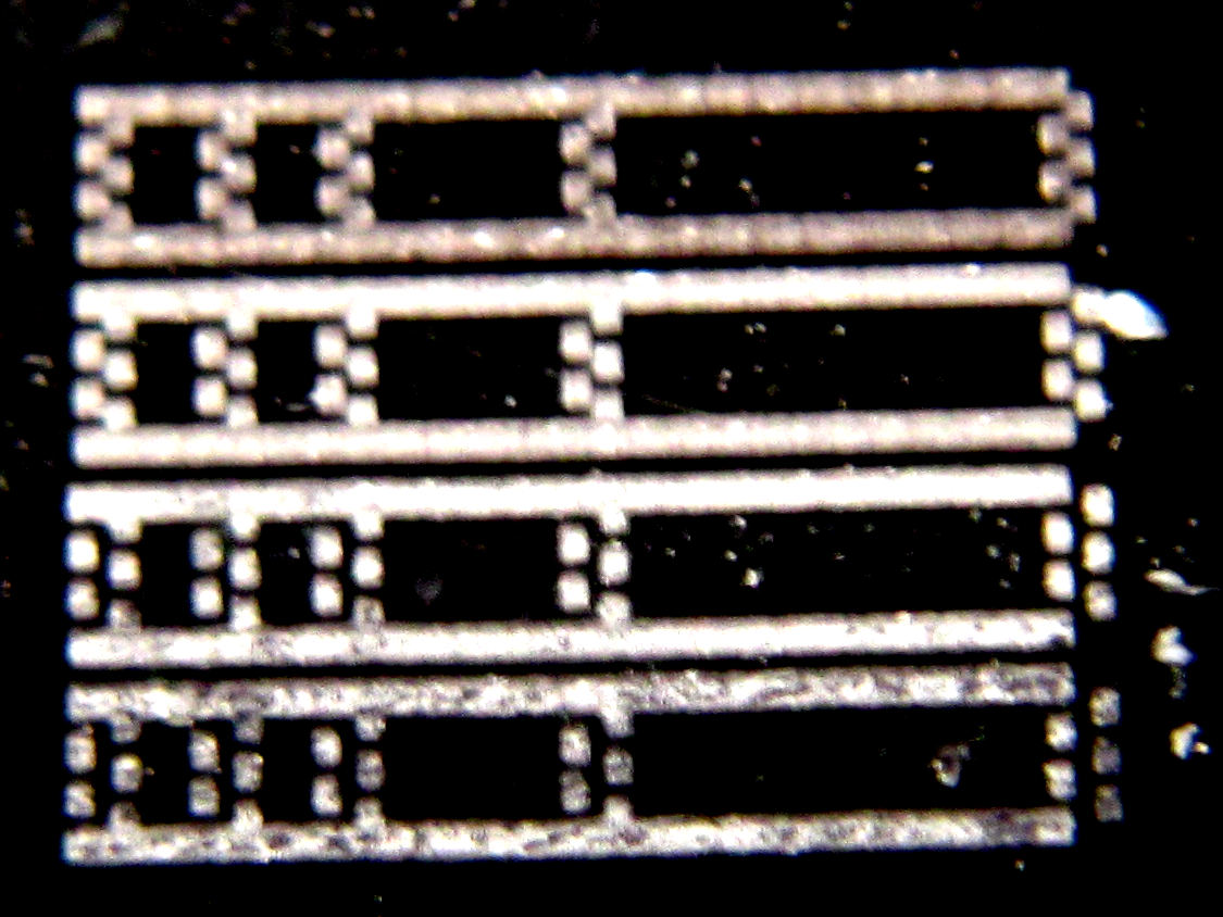
When I received the card, I disassembled it to find that it had a dedicated room for a 75mm fan in it as can be seen below:

I didn't know however if it would be sufficient to cool it, so I installed a temporary CPU fan on it, filling holes with foam:


Then I installed ubuntu-24.04 on an SSD, the amdgpu drivers, rocm stack and built llama.cpp and it initially didn't work. All machines on which I tested it failed to boot, crashed etc. I figured that I needed to have "Above 4G decoding" enabled in the BIOS... except that all my test machines don't have it. I had to buy a new motherboard (which I'll use to upgrade my PC) to test the card.

And there it worked fine, keeping the GPU around 80 degrees C. The card is quite fast thanks to its bandwidth. On Llama-7B-Q4_0, it processes about 1200-1300 tokens/s and generates around 100-110 token/s (without/with flash attention). That's about 23% of the processing speed of a RTX3090-24GB and 68% of the generation speed, for 33% more RAM and 15% of the price!

It was time to try to cut the cover. I designed a cut path using Inkscape and marked it using my laser engraver in order to cut it with my dremel. It's not very difficult, it's just an approximately 0.5mm thick aluminum cover, so it takes around 2 cutting discs and 15mn to cut all this:


Installed the fan, here a Delta 12V 0.24A:


It was also necessary to plug the holes on the back. We're seeing some boards sold with a shroud to hold a loud fan that brings the air from the back because it's wide open. I just cut some foam to the same shape as the back, and after a few attempts it worked pretty fine:


Software testing

Even moderately large models such as Qwen3-30B-A3B-Instruct-2507-Q5_K_L.gguf (MoE) or Qwen3-VL-32B-Instruct in Q4_K_M and Q4_0 quantizations (Q4_0 is quite fast here):

| model                          |      size |  params | backend | ngl | n_batch | n_ubatch | fa |  test |           t/s |
| ------------------------------ | --------: | ------: | ------- | --: | ------: | -------: | -: | ----: | ------------: |
| qwen3moe 30B.A3B Q5_K - Medium | 20.42 GiB | 30.53 B | ROCm    |  99 |    1024 |     2048 |  1 | pp512 | 587.85 ± 0.00 |
| qwen3moe 30B.A3B Q5_K - Medium | 20.42 GiB | 30.53 B | ROCm    |  99 |    1024 |     2048 |  1 | tg128 |  75.65 ± 0.00 |
| qwen3vl 32B Q4_K - Medium      | 18.40 GiB | 32.76 B | ROCm    |  99 |    1024 |     2048 |  1 | pp512 | 216.40 ± 0.00 |
| qwen3vl 32B Q4_K - Medium      | 18.40 GiB | 32.76 B | ROCm    |  99 |    1024 |     2048 |  1 | tg128 |  19.78 ± 0.00 |
| qwen3vl 32B Q4_0               | 17.41 GiB | 32.76 B | ROCm    |  99 |    1024 |     2048 |  1 | pp512 | 278.20 ± 0.00 |
| qwen3vl 32B Q4_0               | 17.41 GiB | 32.76 B | ROCm    |  99 |    1024 |     2048 |  1 | tg128 |  24.50 ± 0.00 |

build: 4206a600 (6905)
I connected the fan to a FAN connector on the motherboard, and adjusted the PWM  to slow it down enough to keep it mostly silent. Around 35-40% speed, the noise is bearable and the temperature stabilizes to 100-104 degrees C while processing large inputs. It's also interesting to see that as soon as the boards switches to generation, it's limited by the RAM bandwidth so GPU cores slow down to a lower frequency and the card starts to cool again.

I noticed that support for this chip was recently merged into the mainline llama.cpp. I tried it, it often shows the same performance except for smaller quantizations like Q4_0 which is a bit slower (~7% on PP, up to 20% on small models like 7B):

| model                          |      size |  params | backend | ngl | n_batch | n_ubatch | fa |  test |           t/s |
| ------------------------------ | --------: | ------: | ------- | --: | ------: | -------: | -: | ----: | ------------: |
| qwen3moe 30B.A3B Q5_K - Medium | 20.42 GiB | 30.53 B | ROCm    |  99 |    1024 |     2048 |  1 | pp512 | 590.24 ± 0.00 |
| qwen3moe 30B.A3B Q5_K - Medium | 20.42 GiB | 30.53 B | ROCm    |  99 |    1024 |     2048 |  1 | tg128 |  76.70 ± 0.00 |
| qwen3vl 32B Q4_K - Medium      | 18.40 GiB | 32.76 B | ROCm    |  99 |    1024 |     2048 |  1 | pp512 | 229.45 ± 0.00 |
| qwen3vl 32B Q4_K - Medium      | 18.40 GiB | 32.76 B | ROCm    |  99 |    1024 |     2048 |  1 | tg128 |  19.86 ± 0.00 |
| qwen3vl 32B Q4_0               | 17.41 GiB | 32.76 B | ROCm    |  99 |    1024 |     2048 |  1 | pp512 | 259.87 ± 0.00 |
| qwen3vl 32B Q4_0               | 17.41 GiB | 32.76 B | ROCm    |  99 |    1024 |     2048 |  1 | tg128 |  24.99 ± 0.00 |

build: db9783738 (7310)

Scaling to two cards

I was convinced and wanted at least another one to see how multiple cards work together. Things began to become quite difficult because apparently the rumor had spread about this card, and prices went crazy, with most being between 380 and 450 EUR, and some even at 1700. I searched for one week, even tried to negotiate with some vendors with no acceptable deal in sight, while prices were still rising. And luckily my vendor recontacted me indicating they had one returned, and they sent it to me at the original price. So I'm now having 7680 cores and 64 GB RAM for 500 EUR shipping included! The only way to beat this is by using the 16GB variant instead but one needs lots of PCIe slots in this case.


I've tried different fans on the new card: 0.45A, 0.55A, 0.70A, and the 0.45A one is quite sufficient and really effective. I should even replace the previous one in the first card with a similar one. Now my two fans spin at around 1500-1600 RPM:
$ cat /sys/class/hwmon/hwmon8/fan{6,7}_input
1536
1480
And the rocm-smi utility shows that both cards are doing well:
$ rocm-smi

=========================================== ROCm System Management Interface ===========================================
===================================================== Concise Info =====================================================
Device  Node  IDs              Temp    Power     Partitions          SCLK    MCLK    Fan     Perf  PwrCap  VRAM%  GPU%  
              (DID,     GUID)  (Edge)  (Socket)  (Mem, Compute, ID)                                                     
========================================================================================================================
0       1     0x66a1,   29631  38.0°C  20.0W     N/A, N/A, 0         930Mhz  350Mhz  14.51%  auto  225.0W  0%     0%    
1       2     0x66a1,   8862   34.0°C  17.0W     N/A, N/A, 0         930Mhz  350Mhz  14.51%  auto  225.0W  0%     0%    
========================================================================================================================
================================================= End of ROCm SMI Log ==================================================
I was initially surprised to see absolutely no change on llama-bench, but found a thread where it was explained that this is normal because llama-bench doesn't use large inputs and it's only on large inputs that the cards can work in parallel (in which case the prompt processing almost doubles but text generation doesn't change). It could allow two users to run in parallel on the llama-server with a higher speed though, but I don't really need this. The real gain for me here is the larger context combined with the ability to load large models. And of course, it's still appreciated to almost double the performance when consuming large prompts.

Another point which is appreciable is when uploading images to be analyzed, because they're processed in parallel by the cards. It was even possible to load Qwen3-235B quantized in TQ1 (1.5625bit):
| model                                   |       size |     params | backend    | ngl | n_batch | n_ubatch | fa | mmap |  test |           t/s |
| --------------------------------------- | ---------: | ---------: | ---------- | --: | ------: | -------: | -: | ---: | ----: | ------------: |
| qwen3vlmoe 235B.A22B IQ1_S - 1.5625 bpw |  50.67 GiB |   235.09 B | ROCm       |  99 |    1024 |     2048 |  1 |    0 | pp512 | 137.10 ± 0.00 |
| qwen3vlmoe 235B.A22B IQ1_S - 1.5625 bpw |  50.67 GiB |   235.09 B | ROCm       |  99 |    1024 |     2048 |  1 |    0 | tg128 |  19.93 ± 0.00 |
137 tokens/s in and 20 token/s out for a 50GB model is quite good (that's due to the MoE architecture, there are in fact 22B active weights at a given moment). I could never do anything with such a large model in the past, even on the Ampere Altra at work since it has only around 5% of this setup's memory bandwidth and processing power. And when dealing with a very large context, a task that took 20 hours on the Altra took one minute here! Now I know for certain that such processing must be done on GPU only.

Power management

I noticed that the boards can automatically control a fan output depending on the temperature and power drawn, but after looking everywhere on the PCB for one hour, I couldn't find any track looking like a PWM output. The fan-like connectors are not connected to anything, and there are empty pads around so it's hard to estimate if it's a pin out of the GPU itself that is supposed to drive the fans, or if it's expected to communicate with an external MCU. Finally I'm connecting the fans to the mainboard and that's fine.

I found that it was possible to reduce the maximum power drawn by the boards. By capping them to 180W, I'm losing around 10% processing capacity, almost no generation capacity, and the cards barely reach 90 degrees C with the fans staying at low speed. For example this is after about 2 minutes of consuming a large input file:

$ rocm-smi -d 0 --setpoweroverdrive 180
$ rocm-smi -d 1 --setpoweroverdrive 180
$ rocm-smi
====================================================== Concise Info ======================================================
Device  Node  IDs              Temp    Power     Partitions          SCLK     MCLK    Fan     Perf  PwrCap  VRAM%  GPU%  
              (DID,     GUID)  (Edge)  (Socket)  (Mem, Compute, ID)                                                      
==========================================================================================================================
0       1     0x66a1,   29631  81.0°C  181.0W    N/A, N/A, 0         1485Mhz  800Mhz  100.0%  auto  180.0W  85%    100%  
1       2     0x66a1,   8862   76.0°C  178.0W    N/A, N/A, 0         1485Mhz  800Mhz  30.2%   auto  180.0W  80%    100%  
==========================================================================================================================
After a long time at full speed it can stabilize:

====================================================== Concise Info ======================================================
Device  Node  IDs              Temp    Power     Partitions          SCLK     MCLK    Fan     Perf  PwrCap  VRAM%  GPU%  
              (DID,     GUID)  (Edge)  (Socket)  (Mem, Compute, ID)                                                      
==========================================================================================================================
0       1     0x66a1,   29631  89.0°C  76.0W     N/A, N/A, 0         930Mhz   350Mhz  100.0%  auto  180.0W  59%    100%  
1       2     0x66a1,   8862   86.0°C  152.0W    N/A, N/A, 0         1485Mhz  800Mhz  30.59%  auto  180.0W  59%    100%  
==========================================================================================================================
Photos taken with a thermal camera confirm these measurements and the fact that the first board is slightly hotter than the second one:


I could probably increase the power limit to 200W to regain a few more percent of processing performance, though it's really not important.

By the way it's visible here that the first card is a bit hotter since its fan is a less powerful (I can adjust that using /sys but here it's not really needed). Another interesting observation is that the boards rarely run with everything at full speed. Either it's the GPU that peaks at 1725 MHz, or it's the RAM that peaks at 1000 MHz, but the card's power management is quite effective at adjusting the frequencies very quickly to the needs. It's in fact super hard to observe both SCLK and MCLK at full speed at the same time above. I never managed to see more than 500W on the mains power meter, and even then it's super rare, the most common power drawn is in the range of 270-330W.
 
I've seen that some users successfully overclock their RAM to 1200 MHz and directly gain 20% text generation speed. Given that the RAM doesn't influence heat that much, it's something I could try, though for now I don't even know where to start given that the driver (or maybe the card's firmware?) enforces the limitations. I'm not going to reflash them though :-)

Caveats

If this card is so great, why isn't it used more ? Just because AMD has dropped support for it in latest ROCm 7.x drivers. It still works to install ROCm 7 and copy all the tensile files having "gfx906" in their names from ROCm-6.4.4 into /opt/rocm/ but it might trigger bugs. I'll need to try again with pure ROCm-6.4.4. This means that in the near future, this board it just going to become e-waste thanks to AMD's pressure to force customers to quickly renew their hardware. It's a shame because it's still an extremely valuable device which has the same amount of RAM as a 5090 and more than 4 times its FP64 processing capacity! It's just not optimal for AI anymore despite being pretty decent compared to commonly available consumer products. Thinking that the cheapest equivalent setup made of three 3090-24GB would cost 5000 EUR, or 10x more than mine explains why this card has become so popular! And AMD showing their customers how they can quickly drop support for well-working products is not something that will convince them to buy their products in the future. At least they won't count me among their customers.

Future

I don't think that AMD will roll back on their decision to drop support for these cards, but for now they allow me to experiment a lot with much larger models than before and with super large contexts that were not practical on CPU only, in order to try to qualify HAProxy patches for backports, see if it's reasonably feasible to spot certain classes of bugs in recent commits, and also help synthetize commit messages to give me summaries of some changes I missed, which helps a lot to prepare the announces for new versions. For the time it works, it's nice. Once it's no longer possible to use these cards, or if it's conclusive and we want to buy something at work, then we'll likely switch to an nvidia or maybe intel, depending on the amount of RAM needed.

I've also seen some videos where people were generating images in less than one second using these cards. I haven't tried this and don't know the software in use yet, but that's clearly among the interesting things to experiment with.

A long time project I had been having that I initially thought about hosting on my Radxa Orion O6 was analyzing and summarizing incoming e-mails. The problem was that large messages could take one minute to be analyzed and I receive quite more than 1440 mails per day, so it would require me to only process some of them. With these cards I could run the same analysis in a few seconds and experiment better without having to pre-filter anything. And given the silent fans I can easily keep the device running full time.

2024-12-08

Adding a cheap and simple RTC to Rockchip devices

Background

There are plenty of nice devices these days designed around ARMv8.2 SoCs such as RK3568 or variations around RK3588. Many of them have been using the HYM8563 I2C RTC chip for about a decade. This device is reasonably cheap, requires few components, consumes very little power and is long proven to work well. Despite its low price, entry-level devices are often lacking it and only have the pads on the board, which is understandable when every dollar counts.  Some such devices include Radxa's E20C and E52C mini routers/versatile servers, which are absolutely awesome devices, which come with either dual-1Gbps or dual-2.5Gbps, feature a USB console so as to always provide a local access, and have a metal enclosure. But they're lacking the RTC, which is quite annoying for a firewall or mini-server, as a power outage always has a painful effect on the dependency chain at home (typically the OS boots faster than the ISP's box and has to start with a bad date). At least once that issue was reported, the products' creator, Tom Cubie (aka @hipboi) acknowledged the problem and suggested that new devices should have it.

Can I do it myself ?

How to proceed with existing devices in the short term ? Isn't it possible to just order the chip and solder it on board ?

One problem with HYM8563 is that it's almost always only found in TSSOP8 format, which means it's a few millimeters wide, with a pitch of 0.65mm, which means that pins are roughly 0.35mm wide with a spacing of 0.3mm between. Actually that's not that difficult to deal with, provided that you have a fine enough soldering iron. The real problem is the components that come around are also of the same scale and very close to each other, as can be seen on the photo of the E52C below (click on the photo to zoom):

The resistors and capacitors are in 0201 format, which is 0.6mm tall by 0.3mm wide, and are very difficult to solder without causing a short circuit. To get a sense of the scale above, the chip is 3mm*3mm. The crystal oscillator is a 32.768 kHz in a flat format that's not easy to find for a hobbyist.

However, the I2C pads (SDA and SCL) are "large enough" and moderately accessible, and there's power on the other side, let's keep that in mind.

Finding a pre-made board

There are various I2C RTC boards available on the net. Most of them are DS1307, and a very nice small one is based on DS3231 with a battery like this one. However, there's no HYM8563 one, and I'd prefer to stay on the same that is referenced in the DTS so that it works out of the box. But I could find the chip alone.

Making a new board instead

Then I started to think whether I could make a board myself based on the chip. Looking at the HYM8563 datasheet above reveals that it's actually not that hard to assemble the few components around. I drew a schematic on by hand (takes one minute vs one hour in Eagle):


I found a few rare occurrences of the chip in SOP8 package, which is easy to deal with, so I could make a PCB with that chip and the 6 components around it. I ordered a pack of 10pcs of that chip, and unfortunately received the tiny TSSOP8 ones instead :-(

But that reminded me that I had some small TSSOP8/SOP8/DIL PCB adapters, which support SOP8 on one side and TSSOP8 on the other side, with the DIL pads in the holes. These are convenient for on-air cabling since pads of both sides are connected together and to the holes:


After all, there were so few components that I could probably solder them directly on that PCB on either side. So let's try.

Bill of materials

Based on the schematic, I'll need this:

  • 1 such PCB
  • 1 HYM8563TS chip
  • 1 diode in 0402 format
  • 2 4.7k resistors in 0402 format
  • 1 82pF capacitor
  • 1 crystal oscillator
  • 1 "large enough" capacitor (I counted about 6mn per 100µF), supporting at least 3.3V


The secret to avoid shorts when soldering TSSOP chips is to use solder paste. I have some in a syringe that I keep cool in the fridge (otherwise it dries in a few months and is unusable the day you need it):

Assembly steps

As a first step, we'll need to cut a trace on the PCB so as to isolate the VCC input pin from its connection to the IC's pin 8, as we'll want to place the diode there instead. We'll need to keep the resistors connected to the external VCC so that the capacitors doesn't discharge its energy into them when off. Thus we'll cut the trace after the via that connects to the other side. What's nice with these boards is that the pads of both sides correspond to the ones of the other side at the same location, so they're easy to match. The final pinout of the board will look like this:

So let's cut the trace:

Now we're going to place the chip before the diode, because it's already painful enough to solder such small chips, we don't want to be hindered by the diode. The approach for this is to place a very little drop of solder paste over all the pads on each side of the chip. Think in terms of volume, considering that the solder paste is mostly flux that will disappear (the flux will avoid shorts by making it difficult for the solder to make bridges between pins). Count that the resulting volume will be roughly 1/3 of the disposed one. Making a small trail roughly as wide as a pad is a good estimate. Make very sure not to leave any beneath the chip, as it will never melt and will stay them forever, risking to make shorts later. Only cover the pads and areas you can clean later. Once done, just place the chip over the paste:

Now solder everything with the soldering iron, without worrying about the risk of shorts, just focus on aligning the chip as best as possible with the pads, and melt absolutely all the paste. Then check with a magnifier or better, a microscope that everything's OK. With a multi-meter you need to check there's no short between adjacent pins:

Now's time to scratch the right side of the track and to place the diode, with the positive on the right and the negative on the left:

Let's now flip the board to solder the resistors. They will attach to the two bottom left pins, and connect to the beneath pad corresponding to the Vdd pin, which is in fact connected to the positive pin at the bottom right. It has the pleasant advantage of being placed immediately next to the two pins, and close enough to have the resistors directly touching on both ends:

Now let's connect the capacitor between the chip's Vss pin and the top rightmost hole that's connected to the chip's pin 1:

On the other side, the oscillator can be soldered. The pins on the left (when reading the reference) or under the notch are the useful ones. The two other ones on the right are not connected so I could connect them to the pin1 pad, though that will depend on the model since some have integrated capacitors and might not work well when doing so, but I could verify with my multi-meter that there was no capacitor there. In order to solder these pins beneath the component, solder paste is your friend again, being cautious again not to put too much:

We're only left with the capacitor that serves as an energy storage during outages. Ideally you'd use 5.5V super capacitors of 0.1F for several days, or the new 3.8V lithium-based supercaps that have even higher capacities (typically 10F and above). But given that my goal here really to just cover occasional power cuts from the mains, when a power supply dies or when I need to move cables inside my rack, I don't need more than a few minutes. And I did happen to have a 4V/150µF capacitor that perfectly matched my needs (should support 7 to 10mn of outage, and was super flat).

Soldering it is just like for the oscillator above except that it's not easy to use solder paste. The positive terminal (the one with the colored bar) needs to be connected to pin 8 of the chip (the top leftmost here) and the negative to the topmost right  hole. Soldering that one is not too hard, just melt some solder inside the hole. Alternately, using thin wires is OK as well.

Now's time to connect wires and test:

I connected these to another board that I'm using for testing I2C, and ran i2cdetect:

Good, the device appears at address 0x51, so at least it's detected. Now we need to verify that its oscillator is properly ticking. For this we'll have to write the current time to the chip (which appears as rtc1 on this board). It will emit an "invalid argument" because it first tries to read the time which contains a bit "VL" ("Voltage Low") set in the second field indicating the the device lost power since last time it was set. But we can ignore it when writing the date, reading it next will indicate whether it works or not (the time must change):

Perfect, it works! Now's time to replace my testing wires with thin ones, to put all of that into shrink tube to protect it and solder it in the device.

Installation

Let's spot the 4 pads we'll need inside the E52C. First, at the bottom of the board, we'll find the I2C SDA and SCL pins at the bottom on these photos, where we'll solder our SDA/SCL wires (violet and green here). They'll have to pass between the board and the enclosure so they must be very thin, but where I'm passing them, there's enough room:


Next step is to install the module on the other side of the board. We're going to glue it on top of the micro SD card reader with some double-sided tape. The capacitor close to it has both positive (3.3V) and negative and is large enough to support soldering directly to it:

Conclusion

It was fun to make but took me most of the day to build; soldering small components requires delicate manipulations, and dealing with flux and solder paste requires lots of cleaning along the operations. I've made two modules so I still have one extra left. This will allow me to migrate another of my machines to a new one, but I'm impatient to see them produced with the chip already soldered so that I don't have to do this anymore!

2024-07-28

Improving A Laser Engraver's Resolution And Accuracy

Baby steps are important

Four years after I wrote about some improvements brought to my Eleksmaker laser engraver, I made quite a lot of progress on multiple fronts.

Laser module

I was regularly annoyed by the too irregular laser beam and finally acquired a NEJE A40640 model that's supposedly 15W optical, made of two diodes and that contains lenses offering a Fast Axis Correction (FAC) to reduce the beam's divergence. The result is an almost square beam that's roughly 60x80 µm by default and can be shrunk to even 60x60 µm at a shorter distance, or be made less than 60 µm wide if made taller.

This constituted the most important improvement because with a poorly shaped beam you can't do any good work. I must say that as of now I think I will never buy again a module without FAC. Think about it, previously if you wanted to cut a circle in wood, half of the circle was completed (e.g. horizontal direction) while the other one was still burning large areas due to the line-shaped beam. Now the same amount of energy is spread in all directions and can be made very narrow.

Air assist

I had been trying various approaches using aquarium pumps to implement some form of air assist to blow the smoke and make a better cut, but these didn't work well. The air flow was made of many irregular pulses and you could hear "puff puff puff" at the output of the laser's head.

I finally decided to order NEJE's air assist accessory for my laser module. Strangely it didn't fit well, it was forcing against the lens' screw. I suspect that the module evolved a little bit since I acquired mine and maybe some dimensions were slightly adjusted on new ones. Nevertheless, I could enlarge the opening of the air assist head so that it fits on my module.


And to get rid of the bad pumps, I finally ordered an AtomStack air pump. The device is really great. It takes 12V input, has a potentiometer to set the air flow speed, and has an output. I just assembled their hose with the one I already had. It further smooths the air flow and now at the output of the module, the flow is super regular and can vary from tiny to quite strong. In practice, most of the time, it's sufficient to set it to 1/4 to 1/3 of the speed in order to blow the smoke away:
 

The results are definitely better, but contrary to what is often seen on ads, it's not on wood that I found the most impressive results, but when engraving images or cutting acrylic. Previously the smoke was causing the beam to diverge a bit, making the result less precise. Now it's super accurate. It's important however to make sure that the piece being worked on doesn't move, because a moving air stream on top of it can make it move (which is another reason for not setting it too strong). That used to be true already for the module's fan anyway. I found that using a few tiny neodymium magnets can be very effective.

Changing the motors' resolution

OK now we're having a nice laser head with much better precision and less disturbances caused by smoke. Isn't that enough ?

In fact I'm using my engraver mostly for PCBs, sometimes for cutting stuff (wood, acrylic), and sometimes to engrave drawings or photos.

For PCBs you do want to have good resolution, otherwise you can't make a track pass between two integrated circuit pins. Or it will touch one side, or be too thin and disappear while etching. With 0.1mm resolution, when you have 0.6mm between two pads of an IC chip, that leaves a single space of 0.1mm on each side, and 0.4mm for the track. Or 0.2mm on each side and 0.2mm for the track. You don't even have an option of 0.15mm each and 0.3mm for the track. And it depends how these are aligned with the motors' steps.

For photos, you generally use Floyd-Steinberg dithering which further reduces the photo's resolution, and when working with 0.1mm dots, that becomes quite visible.

I had been thinking for a long time if it would be possible to find motors with more steps per round. But there was another option that suddenly came to my mind and that I had not yet been considering: what about finding pulleys with less teeth so that it requires more steps to make the same distance ? I searched the net for a few hours and found that the type of belt I'm using is designated as 2GT or GT2 and has a step every 2 mm. My pulleys had 20 teeth and a 5mm axis, and I found others with 16 and even 12. There is a 10-teeth model as well, but only for 4mm axis. So I ordered these, and managed to install the 12-teeth on my motors to replace the 20-teeth one. Here's the photo from the vendor's site:

One assembled, it looks like this (replaced, and with the old one as a comparison):

Doing this requires to adjust the number of steps per mm. It changed from 80 to 133.333 in GRBL's settings, but that's all that needed to be adjusted. I feared that the head would travel slower, but that's not the case. Apparently the speed is more limited by the head's weight and the motors power. However, instead of having a reproducible resolution of 0.1mm, I'm now getting 0.06mm, which precisely is the default size of the beam. Converted to DPI, that's 423 DPI.

This new resolution now allows to export PCBs as images and print them, the result is now good enough. And that's quite convenient because it also means using the same tool for all exports, with the same coordinates system, giving the ability to produce multiple images of various planes, such as the cream plane used to remove varnish and expose solder pads:

In terms of images, this has tremendously improved the result. The dog photo at the bottom is 675x875 pixels and is printed on black-painted aluminum at 0.06mm per dot, resulting in an image of 41x53mm. The result is really impressive, that's 16.6 pixels per mm, or 278 pixels per mm², vs 100 before. That multiplied by 2.78 the pixel density hence the possibilities of nuances in an image.

One problem however is that an image is almost twice as long to print now because there are almost twice as many lines. That was the opportunity for another improvement.

Bidirectional printing

In order to improve print performance, one possibility consists in printing in S form instead of Z, that is, printing even lines from left to right and odd lines from right to left, effectively avoiding a slow return-to-home operation after each line. The software I wrote to convert PNG images to GCODE, png2gcode, already supported such bidirectional printing, but this had always been ugly at high speeds. It was quite visible that there was an offset between each direction. This is not surprising, for three reasons:

  • the startup acceleration is not necessarily the same in both directions. However this was addressed long ago with an option to add an acceleration margin to both sides, that I'm typically setting to 3mm ("-A3") so that the beam arrives at full speed on the first pixel to be printed.
  • micro-stepping is used to control motor positions. Despite using the high-quality TMC 2209 drivers, which take the delivered energy into account to make steps homogenous, it's understandable that the belt's elasticity will not reproduce the exact same position when pulled in one direction or the other, and that it will depend on its tension. Here the belt is quite tight, but tightening it too much can also make it difficult for the motor to make it move in micro-steps.
  • the instruction processing time in the micro-controller counts as well.
Till now, png2gcode would offer an option to set an absolute offset for right-to-left printing (that corresponds to the belt tension), and a time-based offset as well for the processing time. However, approximations that had been used till now were hardly reproducible.

The new laser head combined with the new gears was a great opportunity for trying to improve the situation by taking new measurements.

The test consists in printing on anodized aluminum, a rectangle that's 7 pixels high, 40 pixels wide, with a vertical line at 0, 5, 10 and 20 pixels. When printed only left-to-right ("-Mraster-lr"), it's perfectly regular. When printed in bidirectional mode ("-Mraster"), it's visible that every other line is shifted right by one or a few pixels. The same rectangle was printed at speeds of 600, 1200, 2400 and 3000 mm/min from top to bottom. The pixels are 0.12mm wide. The expected pattern is easier to understand on the top and the deformation is increasingly visible as speed increases. The photo had increased contrast to better see the dots:

This allows to see how much variation there is between them, explaining what is dependent on time, and what is fixed. After some calculation and tests, it appeared that the pixels when going right to left had to be shifted left by 0.12mm and delayed by 2.6ms. This delay is converted to mm depending on the travel speed so that in the end it gives only a distance.

With the right adjustments it's possible to align left-to-right and right-to-left and almost double the print speed. Here's a capture of the final results. It's still visible on the large rectangle that there can be around 10 µm variations in positioning because the vertical lines are not always perfectly straight, but that's very hard to notice on the microscope, let alone to the naked eye! The one on the right was printed at 0.06mm per pixel, and there the positioning resolution remains imperceptible.

The image of the lunch at the top of the sky scraper at the bottom of this page is 1206x943 pixels, rendered on a visit card of 72x56 mm, and took approximately 25 minutes to engrave. With unidirectional printing previously it would have taken approximately 45 minutes (it's not exactly twice as long because the return can be a bit faster when not engraving).

Beam narrowing

As can be seen on the test image below, the beam can be made narrower when it's a bit taller. This is important because if the beam is as large as a pixel, then when it sweeps an area as large as a pixel, it has effectively engraved two pixels. The image shows a test pattern with one dot every 0.12mm (the ruler is in millimeters). A zoom on the dots shows they're between 25 and 30 µm wide and approx 100 µm tall:

We can then exploit this principle to consider that the beam will imprint larger than desired and consider this for granted as soon as the beam turns on.

Example: let's say we want to print the green dashed line below (each square is one pixel the size of the beam). The laser dot (in blue) by default will scan from the left of the square to the right, and will effectively span twice its size. The part that was constantly under the beam will have received more energy, and the borders which were only a limited time under the beam will have received less. As can be seen as the beam advances from left to right (line after line), the pattern is reproduced but the contrast is limited.

Now if we take that beam width into account, we can make the beam start to light up later and extinguish it earlier, still providing a shadow around the borders but leaving the intervals totally unexposed. This is more efficiently done by having the dots twice as large as the beam and reducing the beam duration in half, as this would then preserve the intervals.

When taking all that into account, it becomes possible to print photos on painted metal after passing them through Floyd-Steinberg dithering and produce such stunning outputs:

When zooming in macro mode, it's possible to see the dog's hair as 1/16mm dots:

Similarly, a soom at the center/bottom of the lunch photo, zooming on the metallic beam close to a building shows some of the details, then we can zoom further on the beam and it's visible how the gray is obtained by alternating clear and dark lines:

Wrap up

All of this is a question of patience and experimentation. Now I'm able to easily print a photo on metal by using bright black paint and have enough resolution to almost always do it well on the first pass. In the past I had to adjust power, speed, and color conversion to compensate for the risk of too wide pixels ruining everything. That's no longer the case, as can be seen above with direct printing of photos at very high resolution!